Engine based kinetic energy recovery system for vehicles

a technology of kinetic energy recovery and engine, applied in the direction of hybrid vehicles, positive displacement liquid engines, electrical control, etc., can solve the problems of high energy waste, prior attempts to provide for the recapture of energy for reuse, and difficult economic justification at low energy prices, so as to improve the efficiency of motor vehicles

Active Publication Date: 2005-08-02
INT TRUCK INTPROP LLC
View PDF18 Cites 54 Cited by
  • Summary
  • Abstract
  • Description
  • Claims
  • Application Information

AI Technical Summary

Benefits of technology

[0008]One object of the invention is to improve the efficiency of motor vehicles equipped with internal combustion engines.

Problems solved by technology

It is widely recognized that this arrangement is highly wasteful of energy and that recapture of the energy for use in moving the vehicle from standing starts is desirable.
However, prior attempts to provide for recapture of the energy for reuse, as represented by hybrid gasoline / electric vehicles, have been difficult to justify economically at low energy prices.
However, they are also very complex and as a result cost substantially more to design and build than conventional vehicles.
They also have high maintenance costs associated with periodically replacing the battery plant.
Implementation of systems based on these alternative modes of energy storage have been hobbled by the limitations of the recapture and utilization mechanisms.
Unfortunately, even diesel engines, when operated as pumps, operate at too low of a pressure to provide an efficient and compact kinetic energy capture and utilization system.
In practice only about 300 psi is achieved due to a partial vacuum in the intake manifold and frictional losses.
Absent some modification of a cylinder to operate as a higher compression pump, which complicates the engine and may compromise its performance, the compressed air must be recovered from the exhaust manifold, which entails storage at a still lower pressure.

Method used


Image

  • Engine based kinetic energy recovery system for vehicles
  • Engine based kinetic energy recovery system for vehicles
  • Engine based kinetic energy recovery system for vehicles

Examples


Embodiment Construction

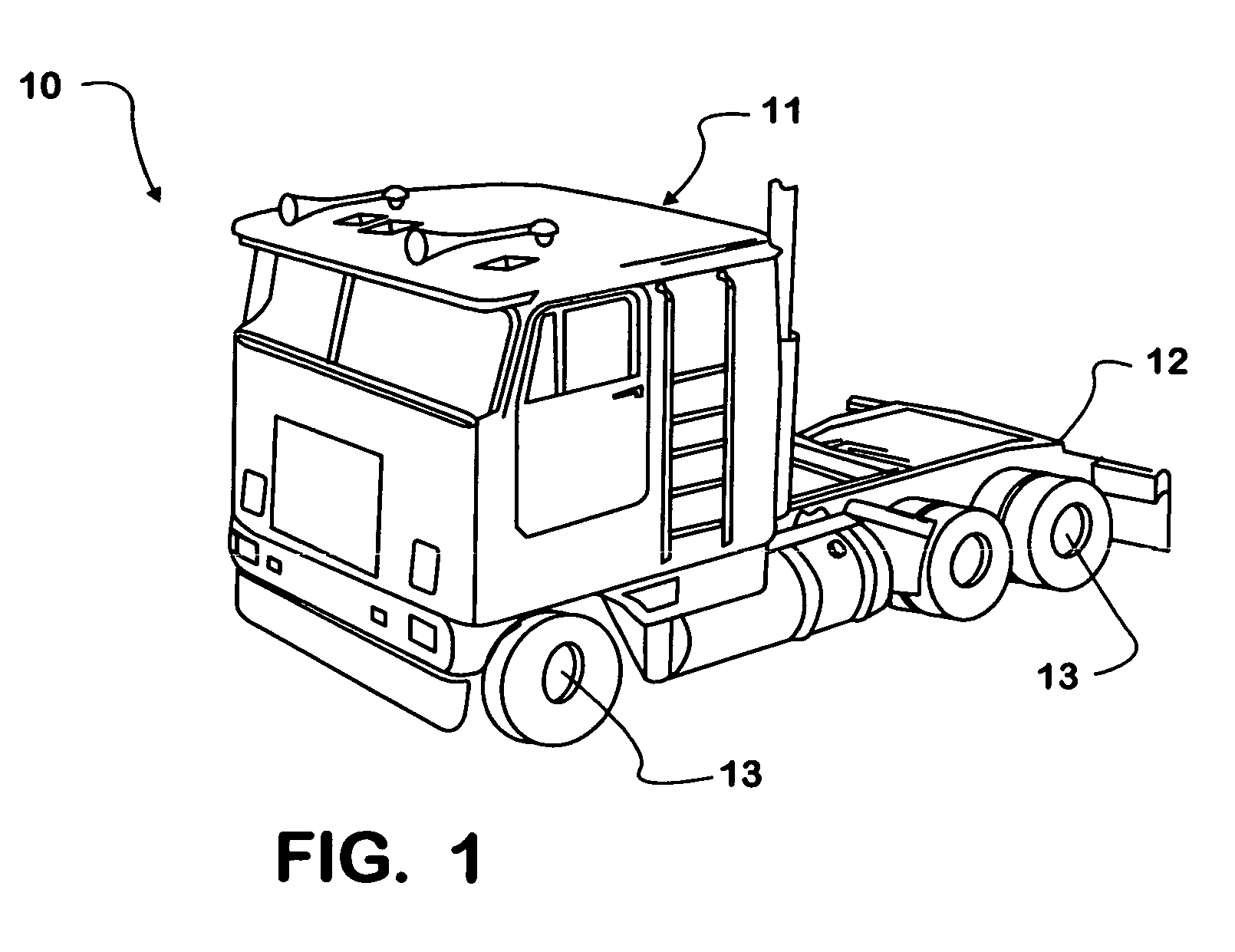
[0022]FIG. 1 illustrates in a perspective view a truck tractor 10 comprising a cab 11 mounted on a chassis 12. A plurality of wheels 13 depend from the chassis. Tractor 10 includes conventional major systems for a vehicle, including a drive train having a diesel engine and a transmission. Tractor 10 also includes air powered drive train boosters as described below. The invention is preferably applied to medium and large trucks which have compressed air systems for brake operation or for starting. These vehicles are typically equipped with a multi-cylinder diesel, which is often adapted for engine compression braking, and compressed air tanks. It will be understood that while the invention is preferably applied to diesels, it would also work, with modification, on internal combustion engines using spark initiated combustion. It may also be advantageously applied to delivery trucks and other vehicles used heavily for stop and go driving.

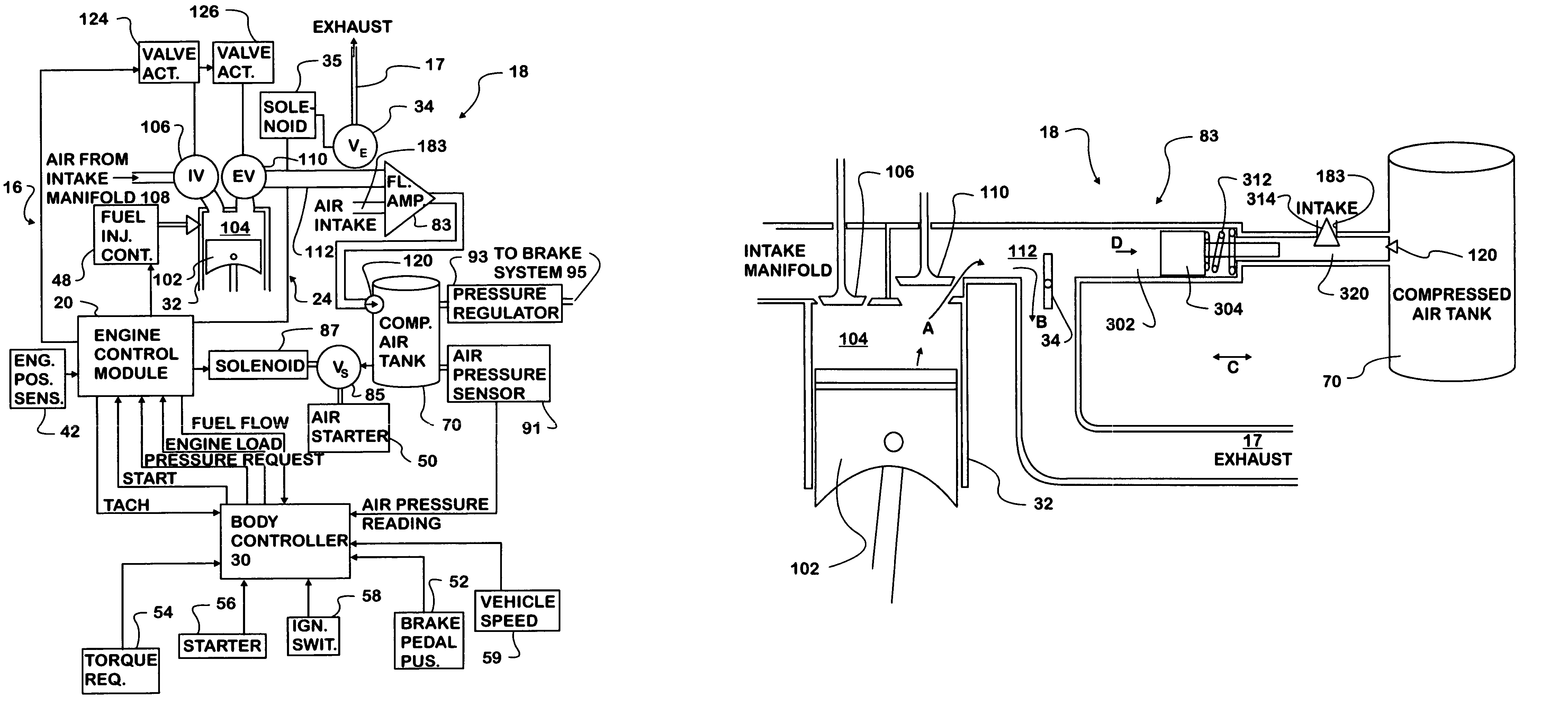
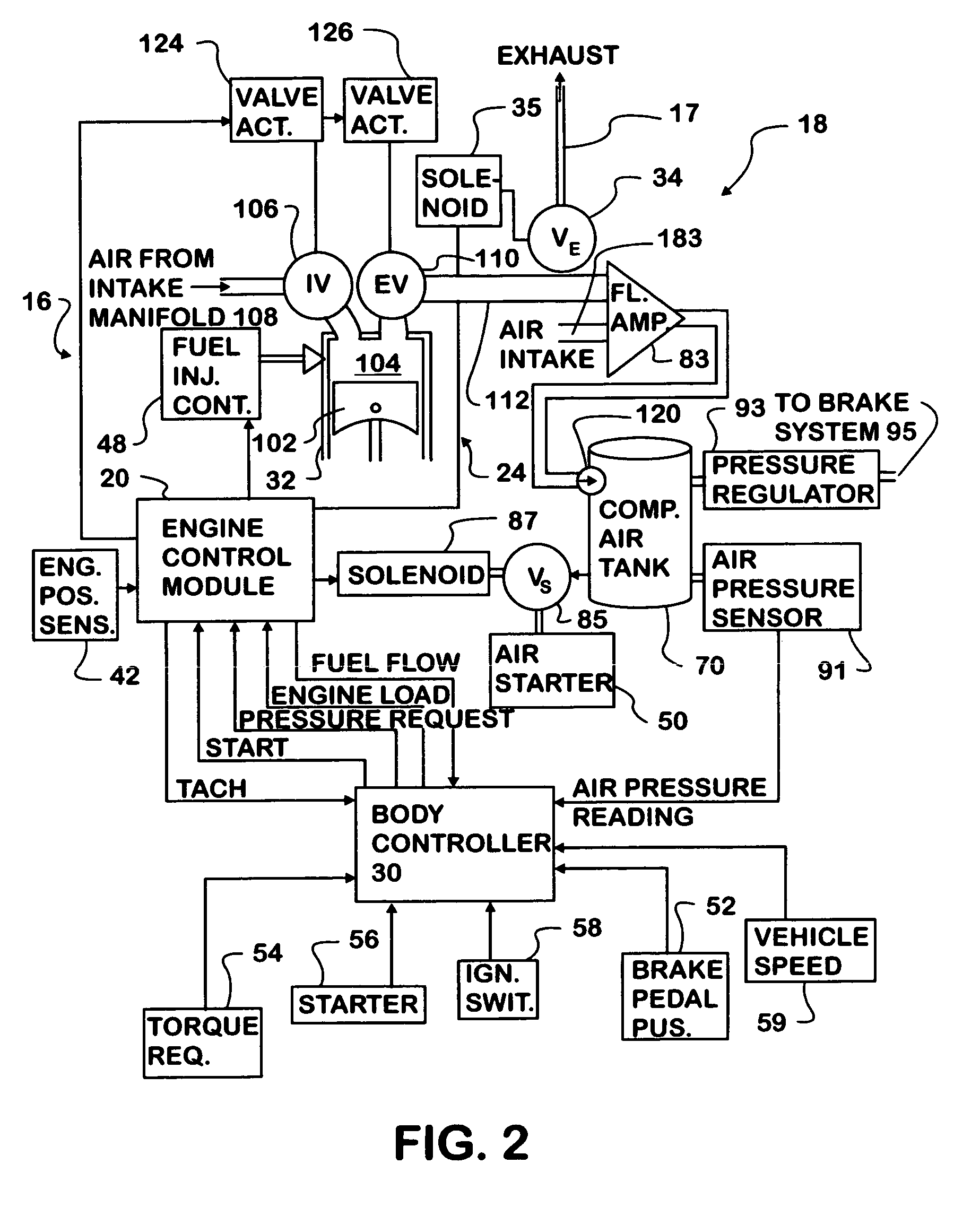
[0023]Referring now to FIG. 2 an engine air comp...


PUM


Abstract

A motor vehicle kinetic energy recovery system uses one or more cylinders of an internal combustion engine as the first or primary stage in a multi-stage high pressure air compression system, a compressed air storage system, compressed air operated drive train boosters and vehicle management electronics to provide cooperation between the air compression, storage and booster systems. The multi-stage, high pressure air compressor system is operable through engine compression braking allowing kinetic energy of a vehicle to be recaptured during retardation of vehicle speed.

Description

TECHNICAL FIELD[0001]The invention relates to vehicles with internal combustion engines and more particularly, to a kinetic energy recovery system for such vehicles.DESCRIPTION OF THE PROBLEM[0002]Most motor vehicles equipped with internal combustion engines dissipate kinetic energy during stopping through use of friction brakes and engine compression braking, rather than capturing and storing the energy for reuse. It is widely recognized that this arrangement is highly wasteful of energy and that recapture of the energy for use in moving the vehicle from standing starts is desirable. However, prior attempts to provide for recapture of the energy for reuse, as represented by hybrid gasoline / electric vehicles, have been difficult to justify economically at low energy prices. These vehicles use both an internal combustion engine and electric motors to move the vehicle. During braking the motors operate as generators to retard the vehicle and convert the vehicle's kinetic energy to ele...

Claims


Application Information

Patent Timeline
Patent Type & Authority Patents(United States)
IPC IPC(8): B60K6/12B60K6/00F02D17/00F02D17/02F02D9/04F02D9/00F02B21/00F02B33/32F02B33/44F02B37/10F02D41/12F04B41/04
CPCB60K6/12F02B21/00F02B33/44F02B37/10F02D9/04F02D17/023F04B41/04F02B33/32F02D41/123Y02T10/6208Y02T10/144B60K2006/123B60K2006/126Y02T10/12Y02T10/62
Inventor LARSON, GERALD L.O'MALLEY, PAUL W.
Owner INT TRUCK INTPROP LLC
Why Eureka
Try Eureka