
Electronic brake control system

Active Publication Date: 2005-08-02
KELSEY HAYES CO +1
View PDF14 Cites 48 Cited by
  • Summary
  • Abstract
  • Description
  • Claims
  • Application Information

AI Technical Summary

Benefits of technology

[0015]The invention further contemplates an enhanced VSC system that corrects vehicle understeer. The system includes the same components described above for the enhanced TC system plus devices for detecting the desired and actual turning directions of the vehicle. The electronic control unit is operative to monitor the turning direction devices during vehicle turning maneuvers for an excessive difference between the desired and actual turning directions that is indicative of a vehicle understeer condition. Upon detecting such an understeer condition, the electronic control unit causes the control valve to selectively apply the rear wheel brake that is on the inside of the turn to reduce the difference between the desired and actual turning directions, whereby vehicle understeer is corrected.
[0016]The present invention also contemplates a method for correcting vehicle understeer comprising the steps of providing a four channel anti-lock brake system that includes devices for detecting the desired and actual turning directions of the vehicle. The system is operative during vehicle turning maneuvers turn to measure the desired turning direction of the vehicle and the actual turning direction of the vehicle. The system compares the actual turning direction of the vehicle to the desired turning direction of the vehicle. Upon detecting a difference between the actual turning direction of the vehicle and the desired turning direction of the vehicle that exceeds a predetermined threshold that is indicative of a vehicle understeer condition, the system applies the vehicle rear wheel brake that is on the inside of the turn. The application of the rear wheel brake reduces the difference between the actual turning direction of the vehicle and the desired turning direction of the vehicle, whereby vehicle understeer is also reduced.

Problems solved by technology

However, with vehicles having driven rear wheels and solid rear axles, such as pickup trucks, it is difficult, and hence expensive, to install a wheel speed sensor for each of the rear wheels.

Method used


Image

  • Electronic brake control system
  • Electronic brake control system
  • Electronic brake control system

Examples


Embodiment Construction

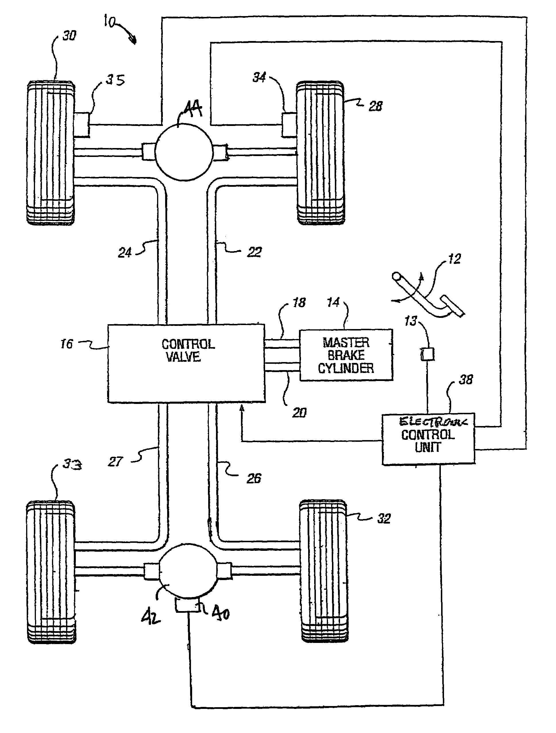
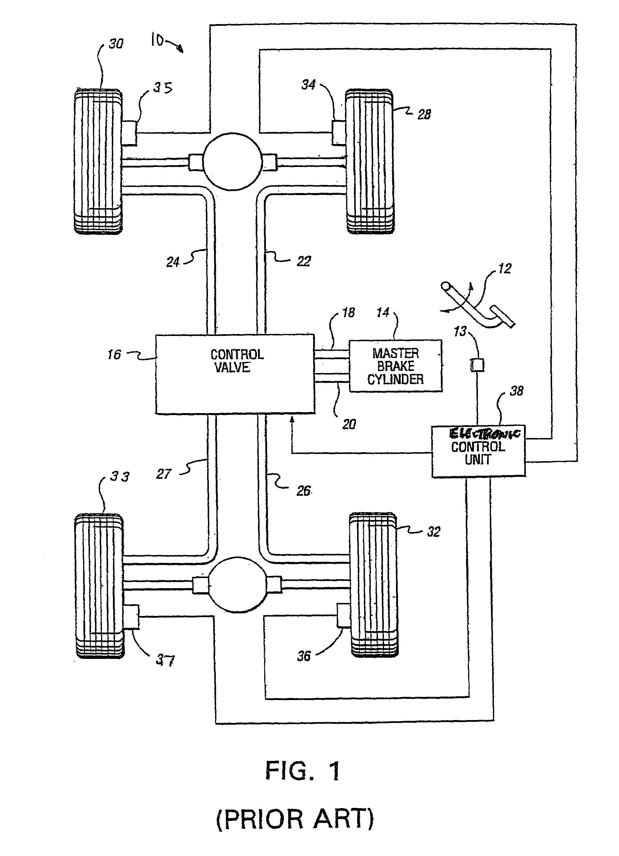
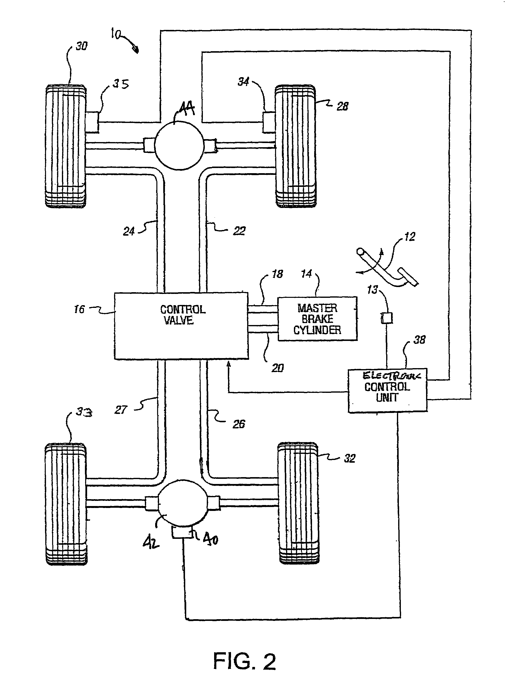
[0027]Referring again to the drawings, there is illustrated in FIG. 2 a schematic diagram of a typical hydraulic brake system 10 for a four wheel drive vehicle equipped with a four channel EBCS that is in accordance with the present invention. Components shown in FIG. 2 that are similar to components in FIG. 1 have the same numerical identifiers. As shown in FIG. 2, the speed of the rear wheels 32 and 33 is monitored by a single conventional rear rotational speed sensor 40 that is mounted upon the vehicle rear differential 42. The rear speed sensor 40 monitors the rotational rate of the rear differential ring (not shown). Alternately, the rear speed sensor could be mounted upon the rear propeller shaft (not shown), which would also be rotating at a speed that is proportional to the average rear wheel speed; or, a speed sensor mounted upon the vehicle transmission (not shown) also could be utilized. Thus, the speed measured by the rear speed sensor 40 is a function of the average spe...


PUM


Abstract

An Electronic Brake Control System having four channels and three wheel speed sensors. The wheel speed sensors include a pair or speed sensors for monitoring the speeds of the individual front wheels and a single speed sensors for monitoring the speed of both rear wheels. The system monitors front wheel speeds during wheel acceleration and, upon detecting excessive slippage of one of the front wheels and the rear axle, applies the front and rear wheel brakes on the side of the slipping front wheel to transfer driving torque to the side of vehicle with a higher coefficient of road surface friction. Alternately, with a four wheel drive vehicle, both rear wheel brakes can be applied to transfer driving torque to the front wheels. The system also senses vehicle parameters during turning maneuvers and, upon detecting an understeer situation, the system is operative to apply one of the rear wheel brakes to correct the undeersteer.

Description

CROSS REFERENCE TO RELATED APPLICATIONS[0001]This application claims the benefit of U.S. Provisional Application No. 60 / 454,140, filed Mar. 12, 2003.BACKGROUND OF INVENTION[0002]This invention relates in general to Electronic Brake Control Systems and in particular to a four channel Electronic Brake Control System that utilizes three wheel speed sensors.[0003]An Electronic Brake Control System (EBCS) is often included as standard equipment on new vehicles. One of the most common such systems is an Anti-lock Brake System (ABS). When actuated, the ABS is operative to control the operation of some or all of the vehicle wheel brakes to prevent wheel lock-up during a brake application cycle. Another EBCS can include Traction Control (TC) which is operative to selectively brake driven wheels that are slipping during vehicle start-ups on low friction surfaces, such as ice or snow. Because of similarity of hardware, an EBCS with TC capability usually includes an anti-lock braking function. ...

Claims


Application Information

Patent Timeline
IPC IPC(8): B60T8/72B60T8/78B60T8/175B60T8/1755B60T8/1761B60T8/34
CPCB60T8/175B60T8/1755B60T8/17616B60T8/1769B60T8/348
Inventor SPIEKER, ARNOLD H.LUBISCHER, FRANK
Owner KELSEY HAYES CO
Learn More