Surgically implantable knee prosthesis having attachment apertures

a surgical implant and prosthesis technology, applied in the field of knee joint prosthesis, can solve the problems of chondromalacia, damage to the surface of the knee joint, degenerative tearing of the meniscal cartilage,

Inactive Publication Date: 2005-08-02
CENTPULSE ORTHOPEDICS
View PDF31 Cites 283 Cited by
  • Summary
  • Abstract
  • Description
  • Claims
  • Application Information

AI Technical Summary

Problems solved by technology

Damage to these surfaces is generally due to genetic predisposition, trauma, and/or aging.
The result is usually the development of chondromalacia, thinning and softening of the articular cartilage, and degenerative tearing of the meniscal cartilage.
In patients with osteoarthritis, degenerative process typically leads to an asymmetric wear pattern that leaves one compartment with significantly less articular cartilage covering the distal portions (or weight bearing area) of the tibia and femur than the other compartment.
As the disease progresses, large amounts of articular cartilage are worn away.
This increasing joint laxity is suspected of causing some of the pain one feels.
All of this shifting of the knee component geometry causes a misalignment of the mechanical axis of the joint.
The misalignment causes an increase in the rate of degenerative change to the diseased joint surfaces causing an ever-increasing amount of cartilage debris to build up in the joint, further causing joint inflammation and subsequent pain.
Currently, there is a void in options used to treat the relatively young patient with moderate to severe chondromalacia involving mainly one compartment of the knee.
Some patients cannot tolerate or do not want the risk of potential side effects of NSAIDs.
Repeated cortisone injections actually weaken articular cartilage after a long period of time.
HA has shown promising results but is only a short term solution for pain.
Arthroscopic debridement alone frequently does not provide long lasting relief of symptoms.
Unfortunately, the lack of long term success of these treatments leads to more invasive treatment methods.
These procedures are not suitable for addressing large areas of degeneration.
In addition, osteochondral allografts can only be used to address defects on the femoral condyle.
Tibial degeneration can not be addressed with this technique.
Howeve...

Method used


Image

  • Surgically implantable knee prosthesis having attachment apertures
  • Surgically implantable knee prosthesis having attachment apertures
  • Surgically implantable knee prosthesis having attachment apertures

Examples


Embodiment Construction

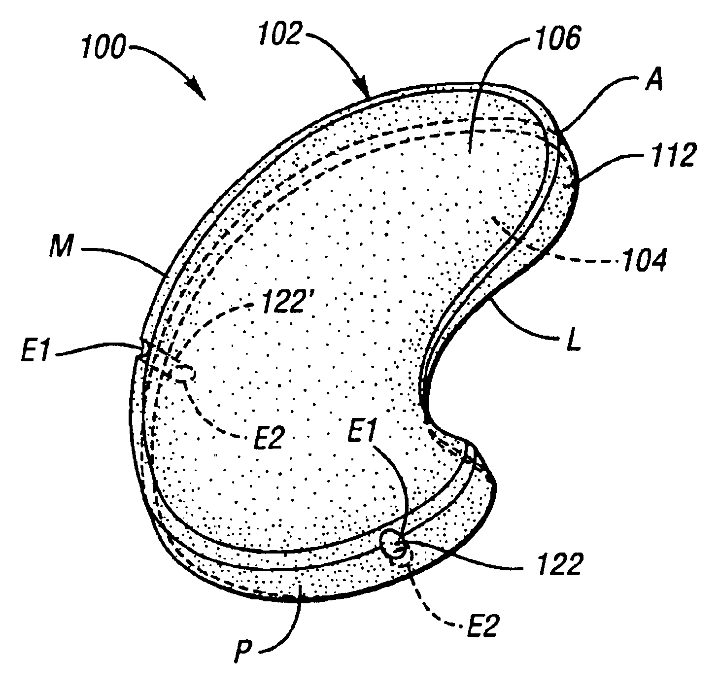
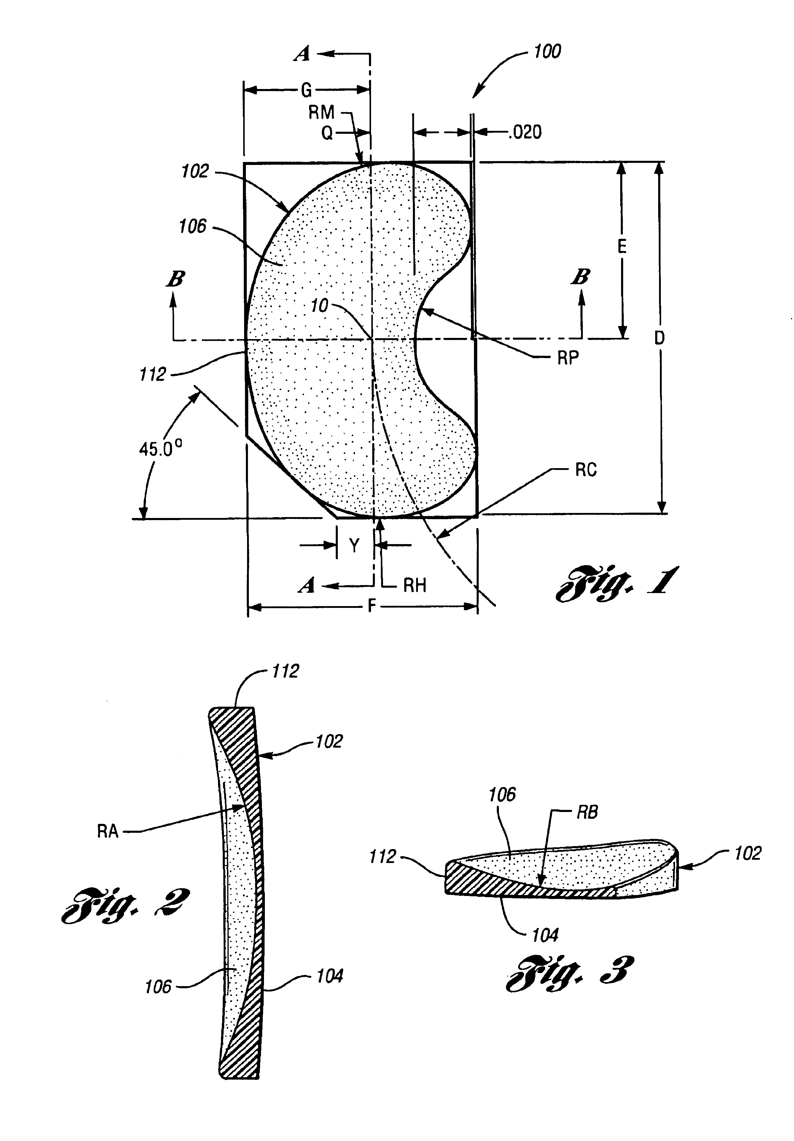
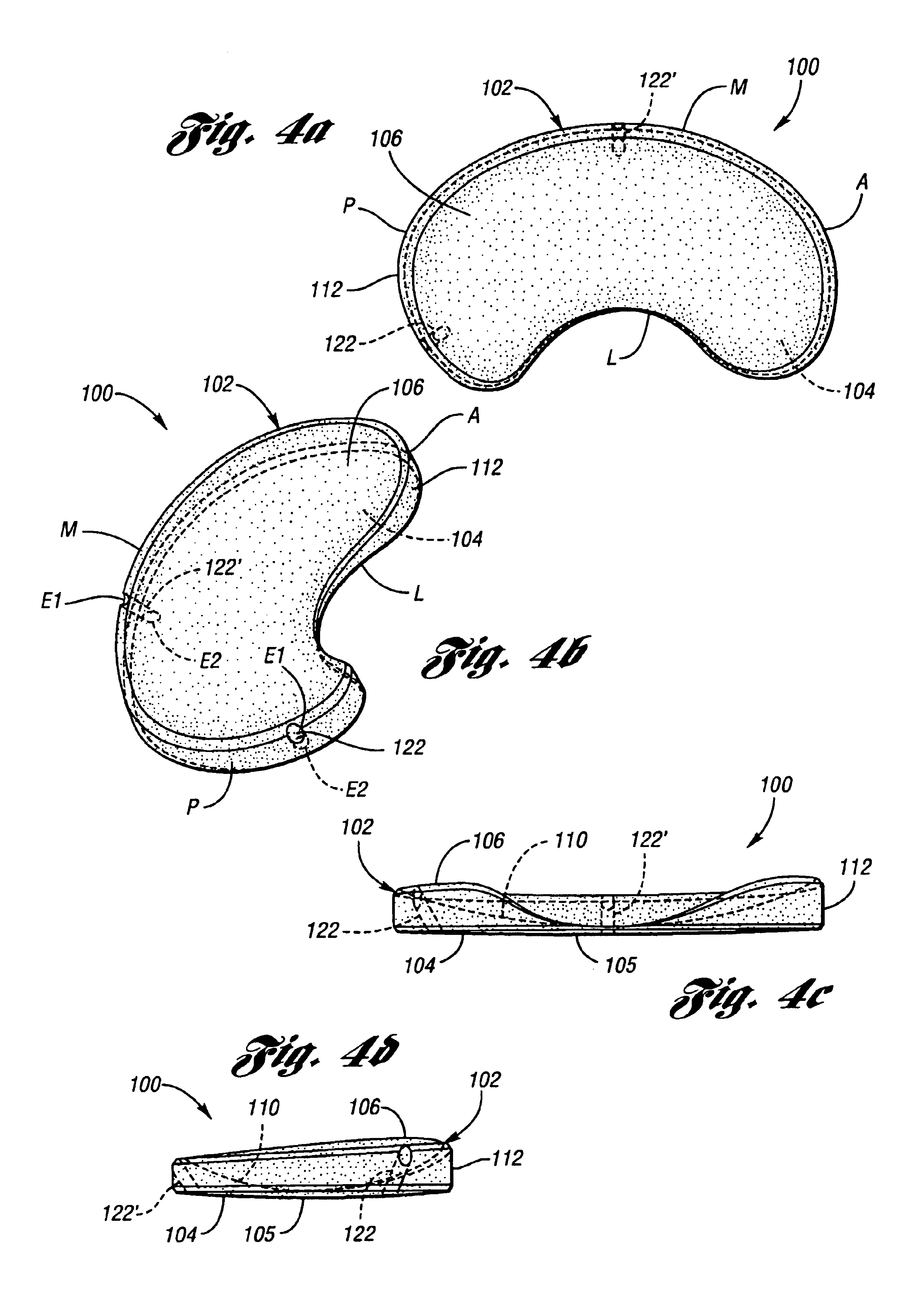
[0025]The present device is an implantable knee prosthesis in the form of a uni-compartmental interpositional spacer which, by effectively replacing worn articular material, restores the normal joint alignment and provides a congruent bearing surface for the femoral condyle to articulate against. Further, it essentially eliminates articulation against the tibial surface thereby preventing further degradation of the tibial surface. Degeneration of the femoral anatomy is significantly reduced because the conforming femoral surface of the device accommodates the complex shape of the femoral condyle in extension as well as in flexion. Insertion of the device is done via a 3 cm to 5 cm medial parapatella incision after arthroscopic debridement of the femoral and tibial cartilage and removal of medial meniscus toward the rim along the anterior, medial and posterior portions. No bone resection or mechanical fixation of the device is required. Only osteophytes which interfere with the devic...


PUM

PropertyMeasurementUnit
Thicknessaaaaaaaaaa
Lengthaaaaaaaaaa
Dimensionaaaaaaaaaa

Abstract

An implantable knee prosthesis for unicompartmental implantation into a knee joint includes a body having a substantially elliptical shape in plan and a pair of opposed faces. A peripheral face extends between the opposed faces and has first and second opposed sides and first and second opposed ends. At least one aperture extends through the body and extends from a first one of the faces to a second one of the faces.

Description

CROSS REFERENCE TO RELATED APPLICATIONS[0001]This application is a continuation of U.S. application Ser. No. 10 / 044,160 filed Jan. 11, 2002, now abandoned.BACKGROUND[0002]The present invention pertains to prosthetic devices. More particularly, the invention pertains to knee joint prostheses which may be surgically implanted between the femoral condyle and tibial plateau of the knee joint.[0003]Articular cartilage and meniscal cartilage provide the mobile weight bearing surfaces of the knee joint. Damage to these surfaces is generally due to genetic predisposition, trauma, and / or aging. The result is usually the development of chondromalacia, thinning and softening of the articular cartilage, and degenerative tearing of the meniscal cartilage. Various methods of treatment are available to treat these disease processes. Each option usually has specific indications and is accompanied by a list of benefits and deficiencies that may be compared to other options.[0004]The healthy knee joi...

Claims


Application Information

Patent Timeline
IPC IPC(8): A61F2/38A61B17/68A61F2/00A61F2/30A61F2/46A61B17/06
CPCA61F2/38A61F2/3872A61B17/06166A61B17/68A61F2/30756A61F2/30767A61F2/30942A61F2/30965A61F2/3868A61F2/4684A61F2002/30026A61F2002/30065A61F2002/30133A61F2002/30324A61F2002/30677A61F2002/30708A61F2002/30762A61F2002/30782A61F2002/30787A61F2002/3895A61F2002/4635A61F2210/0071A61F2230/0015A61F2250/0036A61F2250/0084A61F2310/00017A61F2310/00179A61F2310/0097
Inventor FELL, BARRY M.HALLOCK, RICHARD H.
Owner CENTPULSE ORTHOPEDICS
Why Eureka
Try Eureka