Gas diffuser for head tube assembly of welding gun

a welding gun and diffuser technology, applied in the direction of welding coupling means, welding apparatus, manufacturing tools, etc., can solve the problem of unsupported welding wires within the sealing space, and achieve the effect of improving shielding performance, less complex, and less costly manufacturing

Inactive Publication Date: 2005-08-02
ILLINOIS TOOL WORKS INC
View PDF12 Cites 25 Cited by
  • Summary
  • Abstract
  • Description
  • Claims
  • Application Information

AI Technical Summary

Benefits of technology

[0010]The U.S. Pat. No. 6,225,599 teaches the concept of creating a direct route for the shielding gas to get past the downstream end of the liner and into the contact tip hole, thereby impr

Problems solved by technology

The weld wire is unsupporte

Method used


Image

  • Gas diffuser for head tube assembly of welding gun
  • Gas diffuser for head tube assembly of welding gun
  • Gas diffuser for head tube assembly of welding gun

Examples


Embodiment Construction

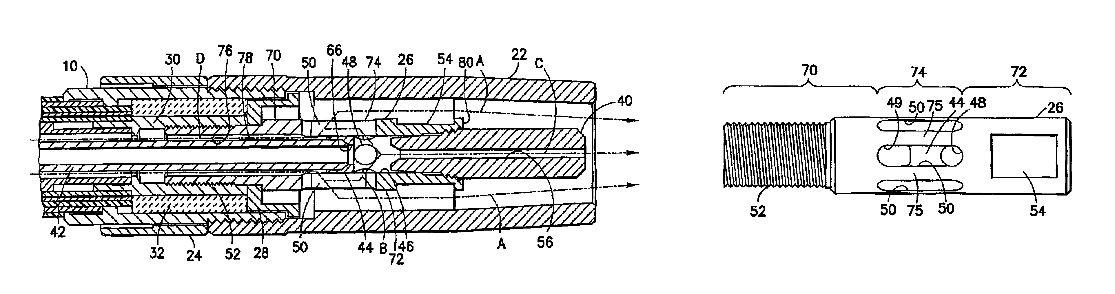
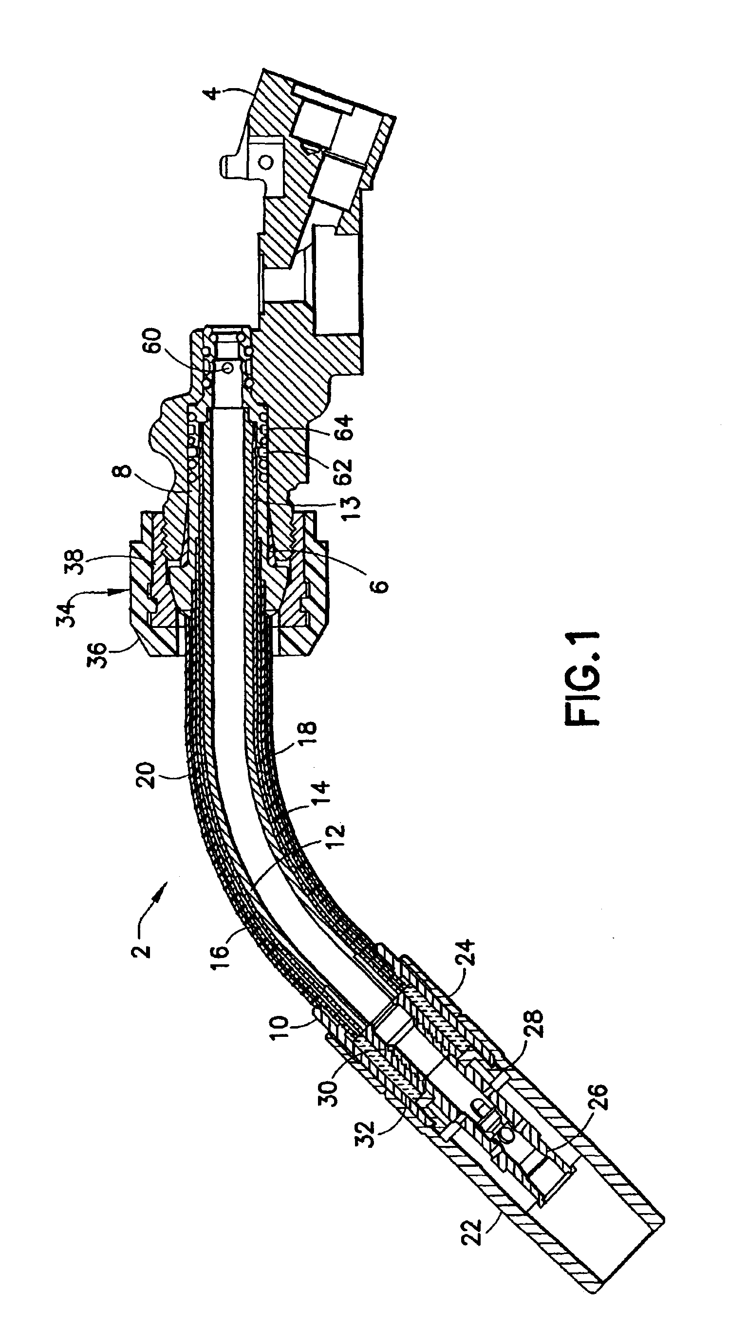
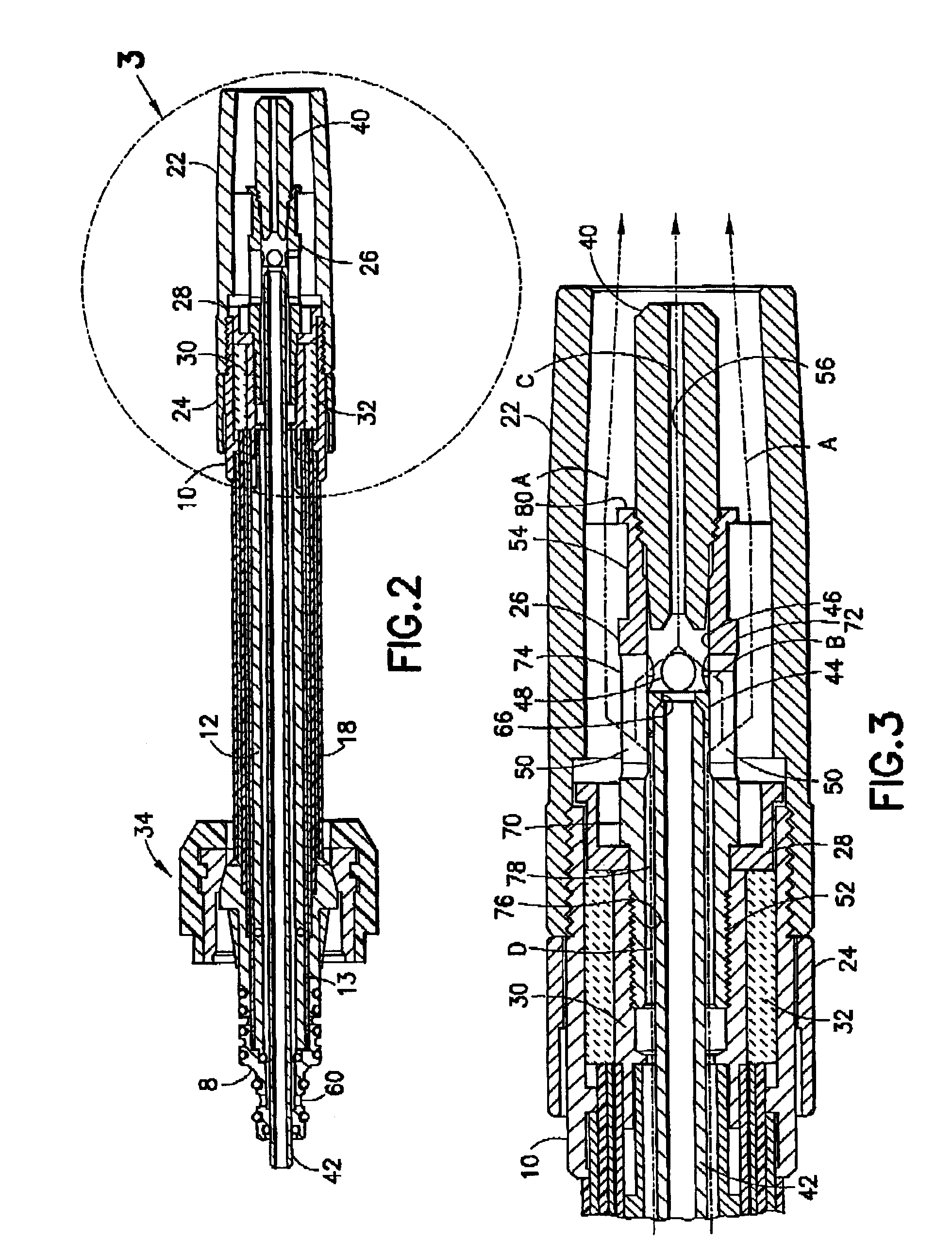
[0023]A head tube assembly in accordance with one embodiment of the invention is shown in FIGS. 1-3. Referring to FIG. 1, a welding gun comprises a head tube assembly 2 mechanically and electrically coupled to an electrically conductive welding gun body 4. The welding gun body 4 has a threaded outer peripheral surface and a cavity defined in part by a frusto-conical inner peripheral surface 6. The head tube assembly 2 comprises respective fittings 8 and 10 brazed to the opposing ends of a tubular structure consisting of an inner copper tube 12, an outer copper sleeve 13, a steel tube 14 surrounding copper sleeve 13, a TEFLON casing 16 encasing steel tube 14, a steel tube 18 surrounding TEFLON casing 16, and an outer TEFLON casing 20 encasing steel tube 18. The end of the copper tube 12 is inserted in and brazed to brass fitting 8. Middle and end sections of the fitting 8, having different diameters, fit inside respective sections of the aforementioned cavity of the gun body 4. Thus,...


PUM

PropertyMeasurementUnit
Angleaaaaaaaaaa
Lengthaaaaaaaaaa
Electrical conductivityaaaaaaaaaa

Abstract

A gas diffuser for a welding gun in which atmospheric air in the interior of the liner is substantially prevented from entering the contact tip hole. The gas diffuser includes a cradle having a hole and a section of a concave surface disposed around a periphery of the hole, and an outer peripheral body having a first axial bore on one side of the cradle and a second axial bore on the other side of the cradle. The outer peripheral body includes one or more generally axial slots, each slot having one end that opens into the first axial bore and another end that opens into the second axial bore. Each slot is open to the exterior of the diffuser along its length and is disposed radially outward of the cradle. The first and second axial bores communicate via the hole in the cradle and via the slots.

Description

RELATED PATENT APPLICATION[0001]This application is a continuation-in-part application claiming priority from U.S. patent application Ser. No. 10 / 272,210 filed on Oct. 16, 2002 and entitled “Head Tube Assembly Having Insulated Mechanical Interface with Welding Gun Body”, now U.S. Pat. No. 6,720,528.BACKGROUND OF THE INVENTION[0002]This invention generally relates to gas metal arc welding (GMAW) and flux core arc welding (FCAW). In particular, the invention relates to wire feeding guns.[0003]Wire feeding guns must perform several different functions in order for successful welding to occur. Those functions include directing the weld wire to the workpiece, conducting electric power to the weld wire, and shielding the welding arc from atmospheric air. In addition to the foregoing basic requirements, it is highly desirable that the weld wire be fed to the workpiece at an adjustable rate that suits the particular welding operation at hand. For maximum productivity, it is also necessary t...

Claims


Application Information

Patent Timeline
IPC IPC(8): B23K9/32
CPCB23K9/323
Inventor MATIASH, NICHOLAS A.
Owner ILLINOIS TOOL WORKS INC
Why Eureka
Try Eureka