Spring loaded bi-stable MEMS switch

a mems switch and spring-loaded technology, applied in the field of switch-stabilizing devices, can solve problems such as inefficient power use, and achieve the effects of simple structure, easy manufacturability and responsiveness, and good responsiveness to the switching member

Inactive Publication Date: 2005-08-02
SUPERCONDUCTOR TECHNOLOGIES INC
View PDF40 Cites 30 Cited by
  • Summary
  • Abstract
  • Description
  • Claims
  • Application Information

AI Technical Summary

Benefits of technology

[0006]By way of non-limiting example, the leaf spring can exhibit a first stable geometry when flexed in one of the opposite directions, and a second stable geometry when flexed in another of the opposite directions. In this case, the leaf spring can have a stress gradient that maintains the leaf spring in the stable geometries. The geometries can be any shape, but in the preferred embodiments, concave and convex geometries, which correspond to the first bending modes of the leaf springs, and advantageously provide good responsiveness to the switching member, are used. Thus, the switch can be switched between two stable states using a momentary force and can maintain these two stable states without further expenditure of energy. In the preferred embodiment, the free end of the cantilever deflects a greater distance than that of the maximum displacement of the leaf spring, e.g., more than twice as great. Thus, in this case, the unique geometry of the switching member acts as a

Problems solved by technology

This results in an inefficient use of power and can be disadvantageous in applicat

Method used


Image

  • Spring loaded bi-stable MEMS switch
  • Spring loaded bi-stable MEMS switch
  • Spring loaded bi-stable MEMS switch

Examples


Embodiment Construction

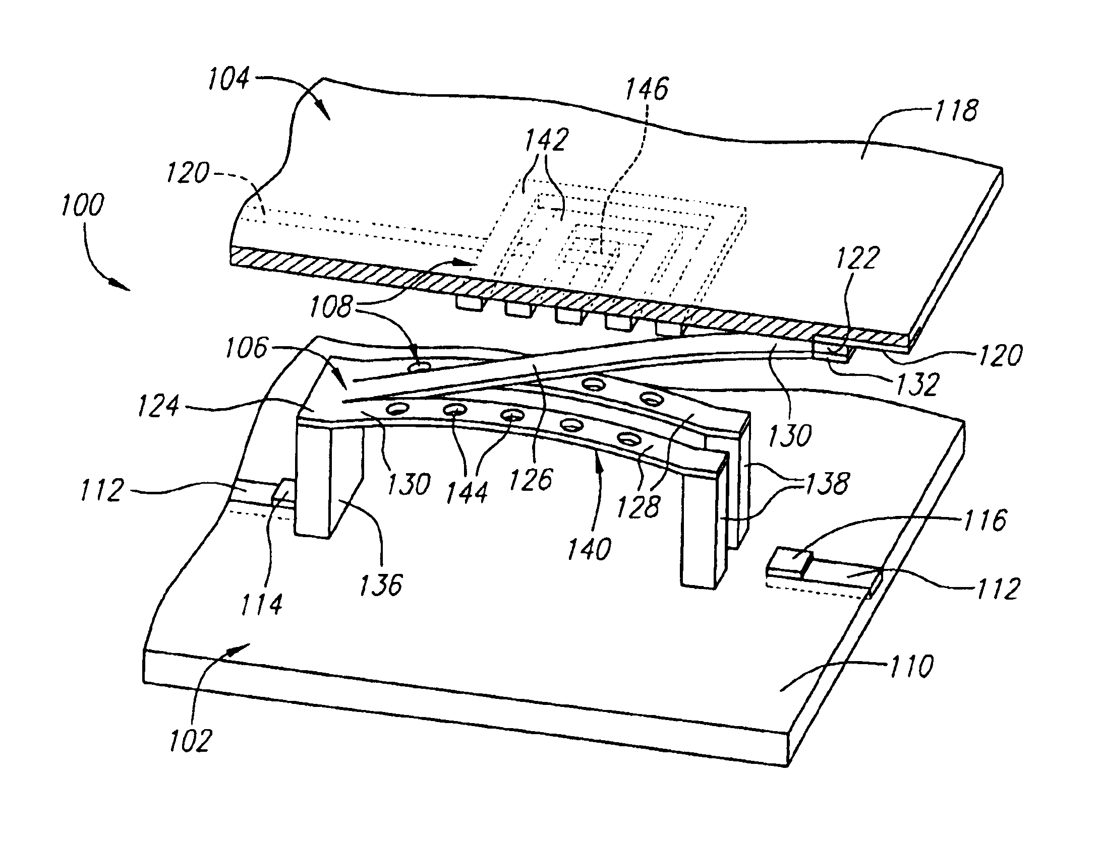
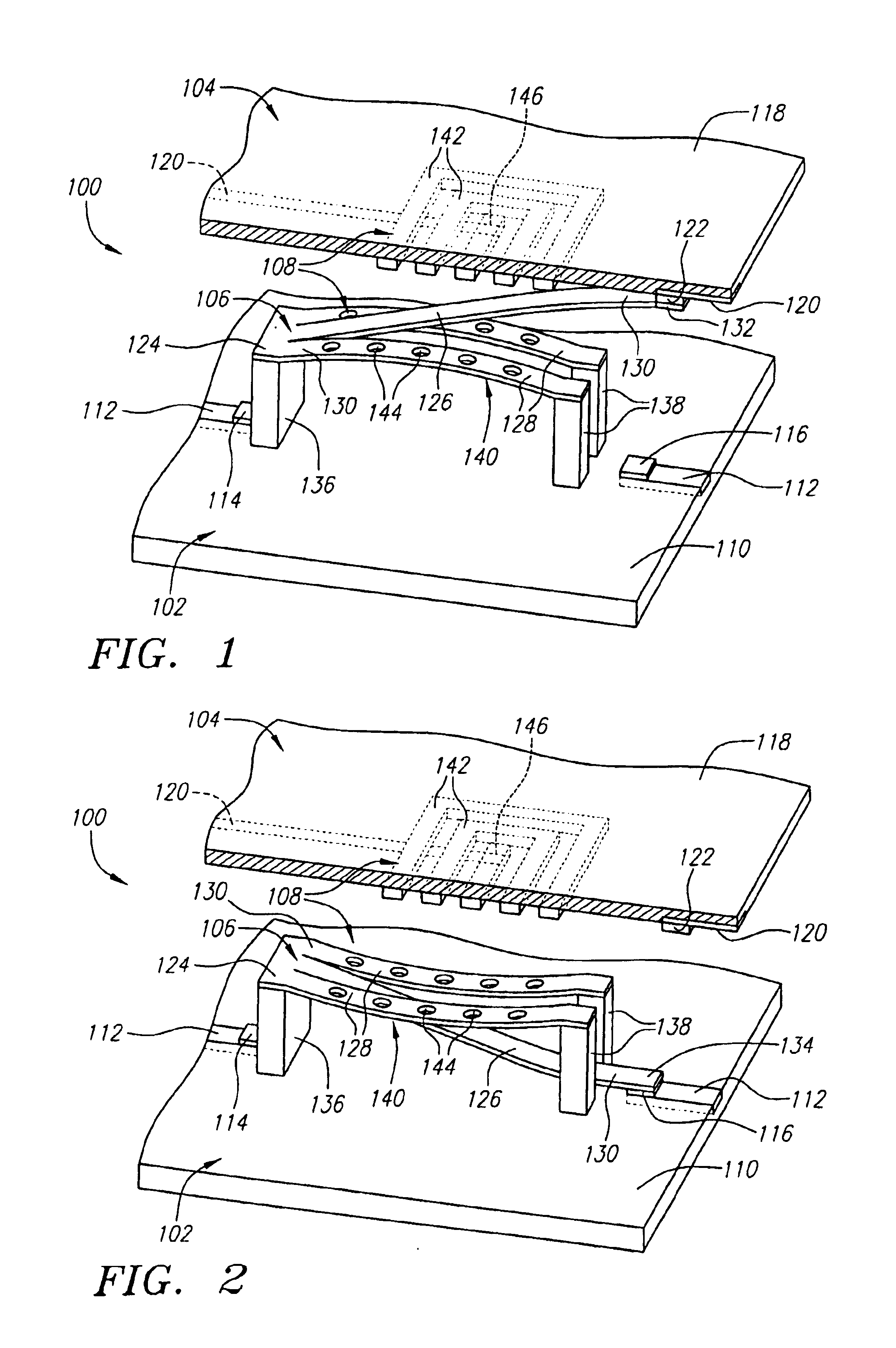
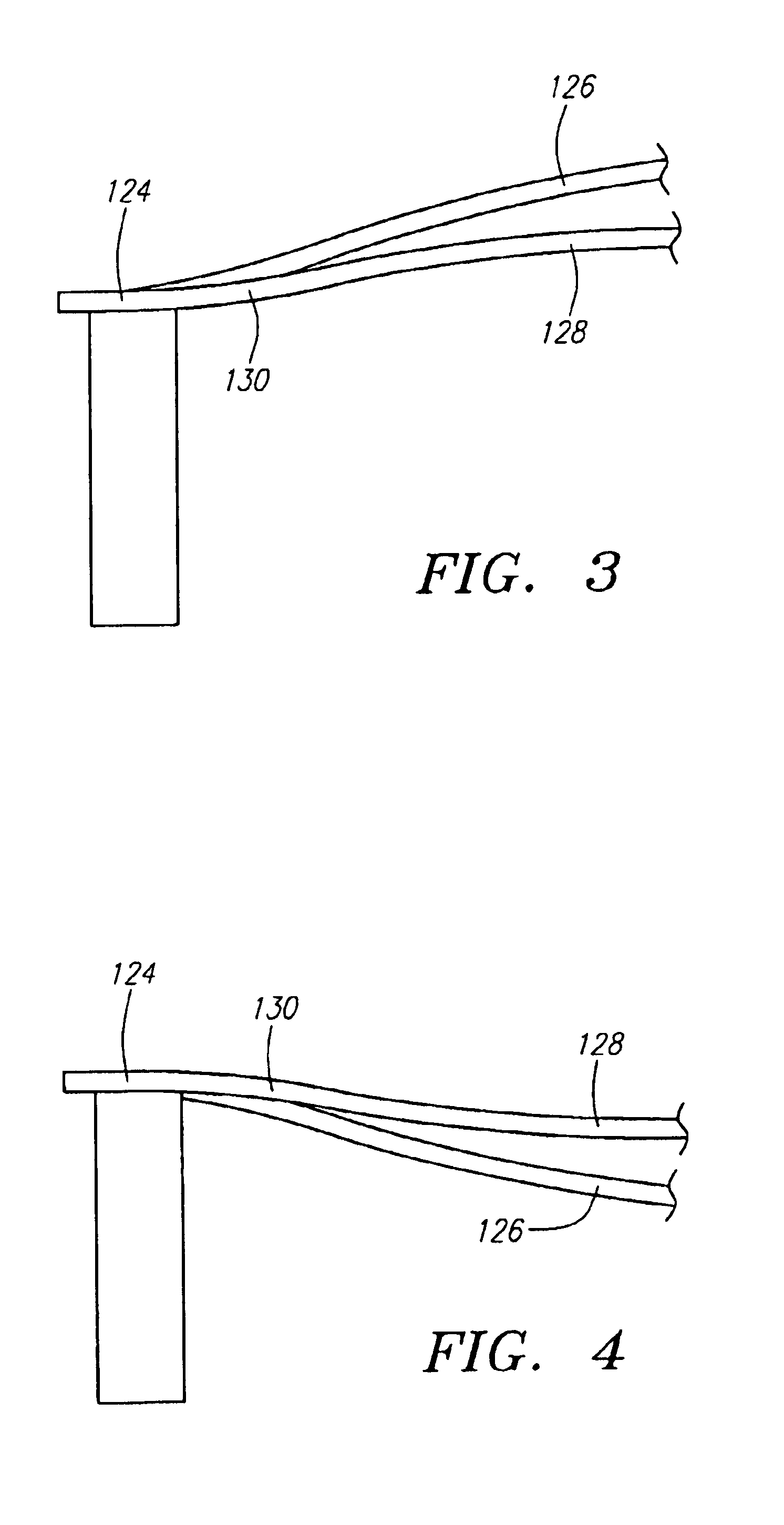
[0027]Referring generally to FIGS. 1 and 2, a spring actuated bi-stable micro-electro-mechanical system (MEMS) radio frequency (RF) switching assembly 100 constructed in accordance with one preferred embodiment of the present inventions will now be described. The switching assembly 100 is bi-stable in that it remains “locked” in one stable state until an applied external force causes it transfer to another stable state, where it is again locked until acted on by another external force. Thus, the switching assembly 100 requires no external force to remain in any of its stable states or positions. It only requires a momentary force to switch from on stable position to the other stable position.

[0028]The switching assembly 100 can be characterized as a single pole double throw (SPDT) switch in that it is configured as a mechanically latching two-chip switch capable of switching a common RF signal between electrically isolated circuits disposed on the respective chips. In this regard, t...


PUM


Abstract

A MEMS switch assembly comprising a substrate and a resilient switching member is provided. The resilient switching member comprises a transverse torsion member having a flexible portion, and a leaf spring and cantilever that extend from the flexible portion of the torsion member. The switching assembly further comprises a first anchoring member mounting the torsion member to the stable structure, and a second anchoring member mounting the leaf spring to the stable structure. In this manner, the leaf spring has a flexible portion between the first and second anchors that can be alternately flexed in opposing directions to deflect the cantilever end in the respective opposing directions. The leaf spring can exhibit a first stable geometry (e.g., a convex geometry) when flexed in one of the opposite directions, and a second stable geometry (e.g., a concave geometry) when flexed in another of the opposite directions. Thus, the switch can be switched between two stable states using a momentary force and can maintain these two stable states without further expenditure of energy.

Description

[0001]The U.S. Government may have a paid-up license in this invention and the right in limited circumstances to require the patent owner to license others on reasonable terms as provided for by the terms of contract no. MDA972-00-C-0010 awarded by DARPA.FIELD OF THE INVENTION[0002]The present inventions generally relate switching devices, and more specifically, to bi-stable switches.BACKGROUND OF THE INVENTION[0003]Micro-Electro-Mechanical System (MEMS) devices find applications in a variety of fields, such as communications, sensing, optics, micro-fluidics, and measurements of material properties. In the field of communications, MEMS Radio Frequency (RF) switches offer several advantages over solid state switches, including a more linear response and a higher quality (Q) factor. Typical MEMS switches require the application of a constant electrostatic or magnetic force in order to maintain the switching assembly in at least one of the desired positions. This results in an ineffici...

Claims


Application Information

Patent Timeline
IPC IPC(8): H01H1/00H01H50/00B81B3/00H01H1/26H01H50/32H01H50/60H01H51/10H01H57/00H01H59/00H01H61/00
CPCH01H1/0036H01H50/005H01H2001/0042H01H2057/006
Inventor PROPHET, ERIC M.
Owner SUPERCONDUCTOR TECHNOLOGIES INC
Why Eureka
Try Eureka