High performance dispersion compensating optical fibers and manufacturing method for the same

a technology of optical fiber and dispersion compensation, which is applied in the direction of cladding optical fiber, manufacturing tools, instruments, etc., can solve the problems of not accurately estimating the dispersion compensation optical fiber, the entire transmission performance will deteriorate, and the sensitive bend loss of optical fiber, etc., to enhance the signal to noise ratio of the transmission system, reduce the attenuation characteristic, and improve the effect of performan

Active Publication Date: 2005-08-02
YANGTZE OPTICAL FIBRE & CABLE CO LTD
View PDF20 Cites 30 Cited by
  • Summary
  • Abstract
  • Description
  • Claims
  • Application Information

AI Technical Summary

Benefits of technology

[0058]The diameter of the large diameter preform manufactured based on this principle is 80 mm˜120 mm, even reaches 160 mm. It is stretched into a preform having smaller diameter, which is less than 60 mm, and the smallest one reaches 30 mm. Then it is drawn into optical fiber directly. The eigen attenuation of the optical fiber can be decreased by controlling the parameters of the core rod through the optimization of PCVD process, and simultaneously, the manufacturing efficiency of the optical fiber is improved and the manufacturing cost is reduced.

Problems solved by technology

For a dispersion compensating module on a transmission link, since it realization of the function of dispersion compensation compromise with the introduction of an insertion loss.
However, this is at the cost of: the optical fiber has low negative dispersion (less than −180 ps / nm.km), and the operating wavelength is near the cut-off wavelength, thereby the optical fiber has a sensitive bend loss and operates unstably.
Chinese Patent CN 1100273C has disclosed a refractive index profile of a dispersion compensating optical fiber and the properties that it can acquire, however, this patent does not relate to the attenuation and the Figure of Merit, so it can not estimate comprehensively the dispersion compensating optical fiber.
In a wavelength division multiplexing system, if the dispersion slope of the transmission link is large, than the deviation between each wavelengths becomes large, and the entire transmission performance will deteriorate.

Method used


Image

  • High performance dispersion compensating optical fibers and manufacturing method for the same
  • High performance dispersion compensating optical fibers and manufacturing method for the same
  • High performance dispersion compensating optical fibers and manufacturing method for the same

Examples


embodiment 1

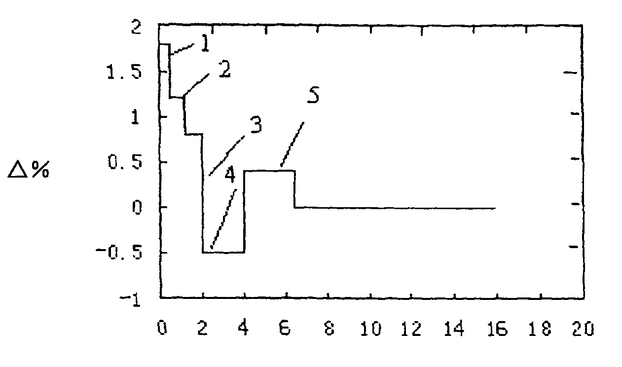
[0042]In embodiment 1, the radii of the respective core sublayers beginning outwardly from the first core sublayer are about 0.6 μm, 1.0 μm, 1.6 μm, 5.0 μm, and 7 μm, respectively; the Δ% (s) of the respective core sublayers beginning outwardly from the first core sublayer are about 1.8%, 1.2%, 0.6%, −0.6% and 0.2%, the cladding layer is a pure Silicon Dioxide glass layer. When manufacturing, a layer is deposited on the inner wall of substrate tube by using PCVD process, which has a certain structure design; the substrate tube is collapsed to form a solid core rod according to a collapsing process; the core rod and a low hydroxyl sleeve is combined by using a RIT process into an optical fiber preform, the diameter of the preform being 80 mm, the diameter of the preform after stretching being 40 mm; and then it is sent into a fiber-drawing furnace for drawing. At 1545 nm, the dispersion of the optical fiber is −160 ps / nm km and the dispersion slope is −0.61 ps / nm km, at 1545 nm, the ...

embodiment 2

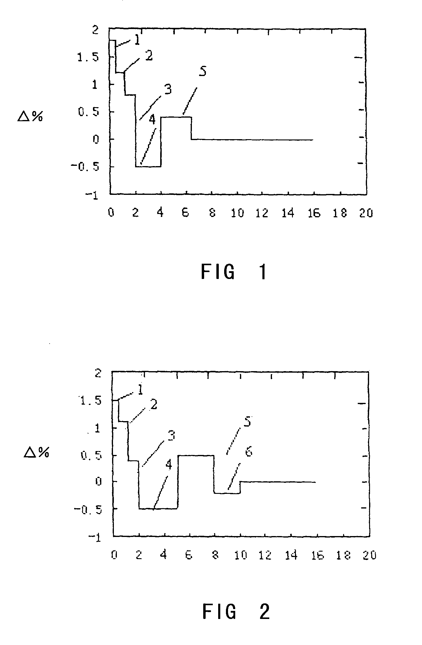
[0043]In embodiment 2, the radii of the respective core sublayers beginning outwardly from the first sublayer are about 0.7 μm, 1.1 μm, 1.8 μm, 5.5 μm, and 8 μm, respectively; the Δ% (s) of the respective sublayers beginning outwardly from the first sublayer are about 2.0%, 1.2%, 0.7%, −0.6%, 0.3%. The diameter of the preform is 120 mm, the diameter of the preform after stretching is 30 mm. At 1545 nm, the dispersion is −142 ps / nm km and the dispersion slope is −0.52 ps / nm km, at 1545 nm, the attenuation of the optical fiber is 0.37 dB / km, the Figure of Merit reaches 383 ps / nm.dB, RDS is 0.0037 nm−1, and the polarization mode dispersion reaches 0.06 ps / km1 / 2.

embodiment 3

[0044]In embodiment 3, the radii of the respective core sublayers beginning outwardly from the first sublayer are about 0.8 μm, 1.2 μm, 2.0 μm, 6.0 μm, 8 μm, respectively; the Δ% (s) of the respective sublayers beginning outwardly from the first sublayer are about 2.1%, 1.4%, 1.0%, −0.4%, 0.4%. The diameter of the preform is 160 mm, the diameter of the preform after stretching is 60 mm. At 1545 nm, the dispersion is −140 ps / nm km and the dispersion slope is −0.55 ps / nm, at 1545 nm, the attenuation of the optical fiber is 0.35 dB / km, the Figure of Merit reaches 400 ps / nm.dB, RDS is 0.0040 nm−1, and the polarization mode dispersion reaches 0.095 ps / km1 / 2.


PUM

PropertyMeasurementUnit
Δaaaaaaaaaa
wavelength rangeaaaaaaaaaa

Abstract

A high performance dispersion compensating optical fiber is provided. In one embodiment, the optical fiber includes a core layer and a cladding layer surrounding the core layer. The core layer includes five core sublayers wherein the □% of the first core sublayer is positive, and the □% of at least one of the other core sublayers is negative, the radius ranges of the respective core sublayers beginning outwardly from the first core sublayer are 0.6 to 0.8 μm, 1.0 to 1.2 μm, 1.6 to 2.0 μm, 5.0 to 6.0 μm, and 7.0 to 8.0 μm, respectively; the ranges of □% of the respective sublayers beginning outwardly from the first core sublayer are about 1.8 to 2.1%, 1.2 to 1.4%, 0.6 to 1%, −0.4 to −0.6% and 0.2 to 0.4%, and the cladding layer is a pure Silicon Dioxide glass layer.

Description

TECHNICAL FIELD[0001]The present invention relates to a dispersion compensating optical fiber and a dispersion compensating module as well as a method for manufacturing the dispersion compensating optical fiber, more specifically, it relates to a method for manufacturing an optical fiber preform by using a plasma chemical vapor deposition method, controlling the refractive index profile and the doped material of the optical fiber to prepare a high performance dispersion optical fiber. The said optical fiber has a low attenuation characteristic and a high Figure of Merit.BACKGROUND ART[0002]The distortion of the signal wave caused by the dispersion of a transmission optical fiber is a constraint factor of the long distance transmission. It is shown by a theoretical analysis that the higher the rate of the transmission system, the smaller the dispersion being permitted. In order to decrease the influence of the dispersion, an effective method currently used to solve the effect of the ...

Claims


Application Information

Patent Timeline
Patent Type & Authority Patents(United States)
IPC IPC(8): C03B23/00C03B23/047G02B6/02
CPCG02B6/02261G02B6/0228G02B6/03688G02B6/02009G02B6/02285
Inventor WANG, TIEJUNCAO, YUQINGLUO, JIE
Owner YANGTZE OPTICAL FIBRE & CABLE CO LTD
Why Eureka
Try Eureka