Implantable medical lead having multiple, jointly insulated electrical conductors

a technology of electrical conductors and medical leads, applied in the field of implantable medical leads, can solve the problems of limited number of cable or wire conductors that can be used, conductors being crossed, etc., and achieve the effects of reducing the number of medical leads

Inactive Publication Date: 2005-08-02
PACESETTER INC
View PDF18 Cites 79 Cited by
  • Summary
  • Abstract
  • Description
  • Claims
  • Application Information

AI Technical Summary

Benefits of technology

[0007]In accordance with one exemplary embodiment, there is provided an implantable lead for transmitting electrical signals between a proximal end and a distal end of the lead, the lead comprising an elongated lead body defining a longitudinally-extending lumen, and a plurality of individual electrical conductors contained in the lumen of the lead body and extending between the proximal and distal ends, the plurality of individual conductors sharing a common insulating coating. Preferably, each of the plurality of individual electrical conductors may comprise a multifilar cable conductor of, for example, MP35N or MP35N / Ag alloy for superior flexibility and fatigue life. Alternatively, each of the plurality of individual electrical conductors may comprise a non-coiled monofilament wire of, for example, nitinol or MP35N.
[0008]According to one specific form of the invention, the common insulating coating electrically isolates the plurality of conductors from each other and may include a bridging portion extending between the individual conductors. The bridging portion of the common insulating coating may be perforated to impart additional flexibility to the coating.
[0009]According to another specific form of the invention, the conductors may be placed in electrical contact with each other along their lengths within the insulating coating. Such a configuration has a higher current-carrying capacity.
[0010]Pursuant to another aspect of the present invention, the plurality of electrical conductors and the common insulating coating comprise a conductor assembly. The conductor assembly in accordance with one form thereof may have a helical configuration defining a longitudinally-extending passageway for receiving a stylet, guide wire or the like for placing the distal end of the lead within the heart. In this helical configuration of the conductor assembly, the common insulating coating preferably has, in cross section, a generally oval shape with its longer dimension extending in the longitudinal direction. The plurality of individual conductors are preferably spaced apart in the longitudinal direction within the generally oval shaped common insulating coating to minimize the outer dimension of the lead body.
[0011]Pursuant to another form thereof, the conductor assembly may have a tubular configuration. The plurality of individual conductors is embedded within the common insulating coating of the tubular conductor assembly and may be arranged in spaced-apart, parallel relationship. Alternatively, the embedded plurality of conductors may follow a generally helical path along the length of the lead body for greater lead body flexibility.
[0012]The lead of the present invention provides a robust structure while reducing the number of components thereby simplifying the lead structure and decreasing manufacturing costs. The jointly coated, multiple conductor assemblies of the invention are more easily handled during production; for example, they can be threaded in a single operation and eliminate the problem of crossing conductors during assembly. Further, the multiple conductors of a jointly coated conductor assembly may be ablated in a single operation instead of the current time-consuming method of separately ablating each individually coated conductor.

Problems solved by technology

In the first design, the number of cable or wire conductors that can be used is limited by the cross sectional area limitations of the lead body.
In the second design, although multiple cable or wire conductors within a common lumen can allow for a smaller diameter lead, this design often entails inefficient, time-consuming individual conductor preparation and lead assembly, and may result in conductors being crossed during assembly.
Further, the multiple conductors of a jointly coated conductor assembly may be ablated in a single operation instead of the current time-consuming method of separately ablating each individually coated conductor.

Method used


Image

  • Implantable medical lead having multiple, jointly insulated electrical conductors
  • Implantable medical lead having multiple, jointly insulated electrical conductors
  • Implantable medical lead having multiple, jointly insulated electrical conductors

Examples


Embodiment Construction

[0019]The following description presents preferred embodiments of the invention representing the best mode contemplated for practicing the invention. This description is not to be taken in a limiting sense but is made merely for the purpose of describing the general principles of the invention whose scope is defined by the appended claims.

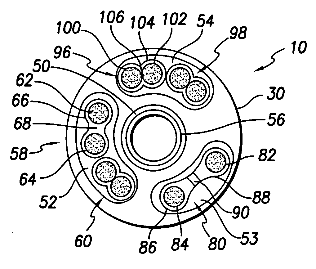
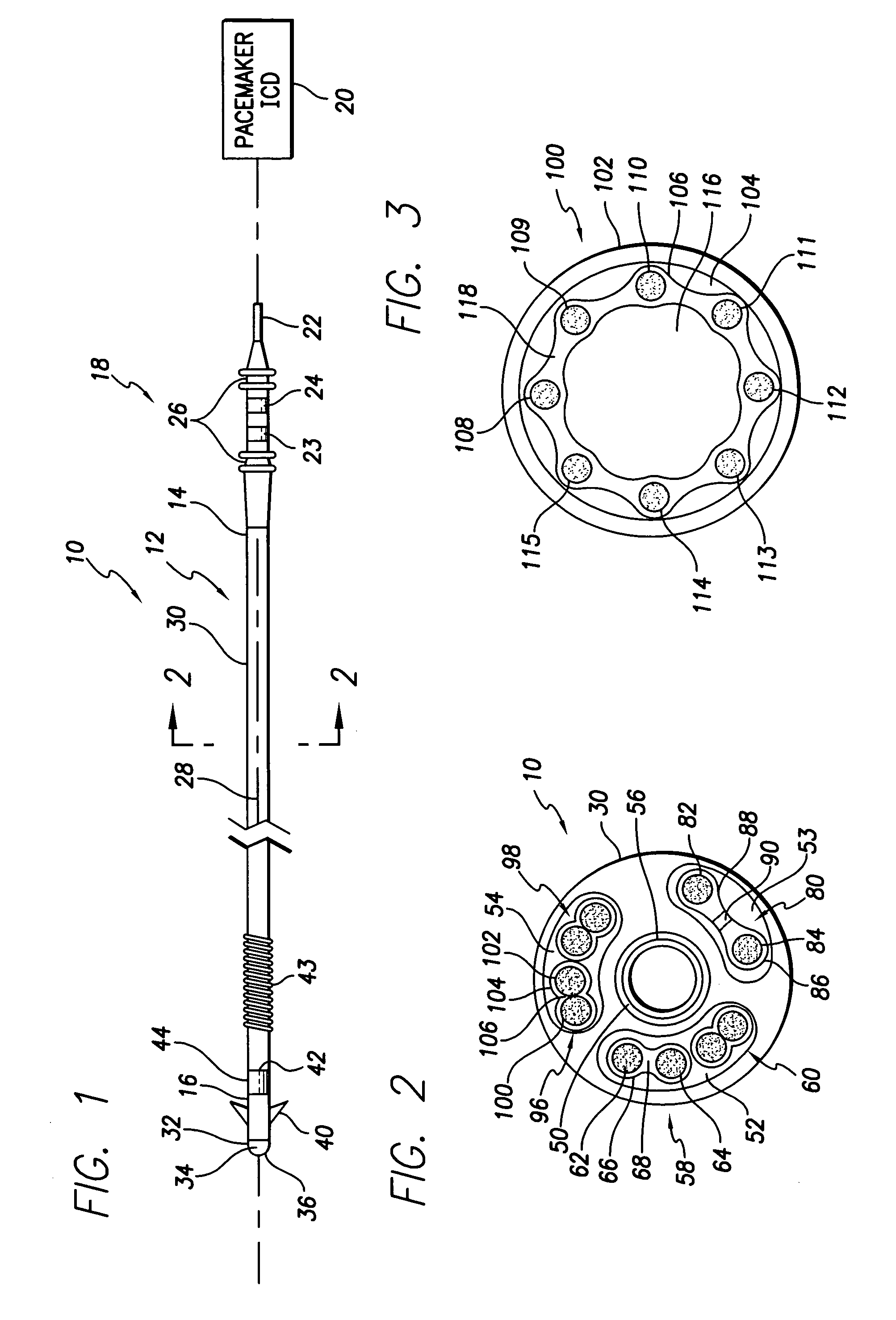
[0020]FIG. 1 shows an endocardial pacing, sensing and defibrillation lead 10 including a lead body 12 having a proximal end 14 and a distal end 16. The lead 10 is illustrated to be of a bipolar design, but is not intended to be limiting of the invention. The proximal end 14 of the lead incorporates a connector assembly 18 compatible with a standard such as the IS-1 standard for connecting the lead body 12 to an implantable medical device in the form of a pacemaker / ICD 20. The connector assembly 18 includes a tubular pin terminal contact 22 and ring terminal contacts 23 and 24 electrically coupled to electrodes along the distal end of the lead body....


PUM


Abstract

An implantable lead for transmitting electrical signals between a proximal end and a distal end comprises an elongated lead body defining a longitudinally-extending lumen, and a plurality of individual electrical conductors contained in the lumen of the lead body and extending between the proximal and distal ends, the plurality of individual conductors sharing a common insulating coating. Each of the plurality of individual electrical conductors preferably comprises a braided, multifilar cable conductor. In one embodiment, the common insulating coating electrically isolates the plurality of conductors from each other, and may include a bridging portion extending between individual conductors.
The plurality of electrical conductors and the common insulating coating comprise a conductor assembly that may have a helical configuration defining a longitudinally-extending passageway for receiving a stylet, guide wire, or the like, for placement of the distal end of the lead. Alternatively, the conductor assembly may have a tubular configuration, the plurality of individual conductors being embedded therein in spaced-apart, parallel relationship or along a generally helical path along the length of the lead body for greater lead flexibility.

Description

FIELD OF THE INVENTION[0001]The present invention relates generally to implantable medical leads and particularly to reduced diameter implantable leads employing multiple electrical conductors.BACKGROUND OF THE INVENTION[0002]Many of today's intravascular endocardial leads are multipolar leads typically comprising a tip electrode and one or more ring electrodes disposed along the distal end of the lead body. The various electrodes transmit electrical stimulation pulses from an implantable medical device such as a pacemaker or implantable cardioverter defibrillator (ICD) to the tissue to be stimulated, and / or transmit naturally occurring sensed electrical signals from the tissue to the medical device. In a typical bipolar lead having a tip electrode and a ring electrode, two helically wound conductor coils with insulation in between are arranged coaxially and carried within a single lumen of the lead body. The inner conductor coil connects the medical device with the tip electrode wh...

Claims


Application Information

Patent Timeline
Patent Type & Authority Patents(United States)
IPC IPC(8): A61N1/05
CPCA61N1/056
Inventor SALYS, SCOTT
Owner PACESETTER INC
Why Eureka
Try Eureka