Following stage planar motor

a planar motor and following stage technology, applied in the field of two-dimensional electric motors, can solve the problems of affecting the free movement of the coil assembly, affecting the smooth and accurate positioning of the platform of the two-dimensional electric motor, and affecting the timing of the applied current. achieve the effect of large range of motion

Inactive Publication Date: 2005-08-09
NIKON CORP
View PDF9 Cites 36 Cited by
  • Summary
  • Abstract
  • Description
  • Claims
  • Application Information

AI Technical Summary

Benefits of technology

[0017]The present invention seeks to provide a planar stage motor that exploits advantageous features of conventional stacked designs while eliminating disadvantages that conventionally accompanied such stacked designs. The invention provides a six-degree-of-freedom planar motor that uses a following stage. A purpose of the invention is to control the position of a wafer stage, or other object, in all six degrees of freedom. The present invention uses linear motors to achieve planar motion of a stage with a large range of motion. Because a following stage may be used to carry the stator part of the linear motors for one axis, a large range of motion is possible with a relatively compact stage.

Problems solved by technology

However, each additional phase group complicates timing of the applied current to the various phase groups.
When used to position a platform, conventional two-dimensional electric motors do not smoothly and accurately position the platform.
Unfortunately, the hoses and cables impede free motion of the coil assembly.
Also, in many cases conventional technology relies upon cumbersome stacked arrangements to achieve six degrees of freedom movement of the platform.
Unfortunately, many designs obtain six degrees of freedom by essentially stacking multiple two dimensional and / or one dimensional motors which move only in two dimensions within a plane.
Also, the complicated joint connections degrade accuracy of positioning of the platform and create additional resonant vibration frequencies.
Second, these single actuator designs often result in coupling between forces in different directions.
However, because of manufacturing variations, changes in the magnetic gap, and other disturbances, the forces produced by each coil do not exactly match theory.
Therefore, producing force in the x direction will lead to some force ripple in y and z. Also, the effects of cross-axis force ripple limit the planar motor's ability to precisely control the position of the stage.
Conventional linear motors have not resolved these problems of single actuator motor designs.
Linear motors that address this problem with limited range of motion have the drawback of requiring motor structure on both sides of the stage.
Often the parts of the motor on the top of the stage interfere with other sensors or equipment.
Also, such a design requires a relatively large stage.
These various disadvantages of conventional linear motors detract from their efficiency, performance and usefulness.

Method used


Image

  • Following stage planar motor
  • Following stage planar motor
  • Following stage planar motor

Examples


Embodiment Construction

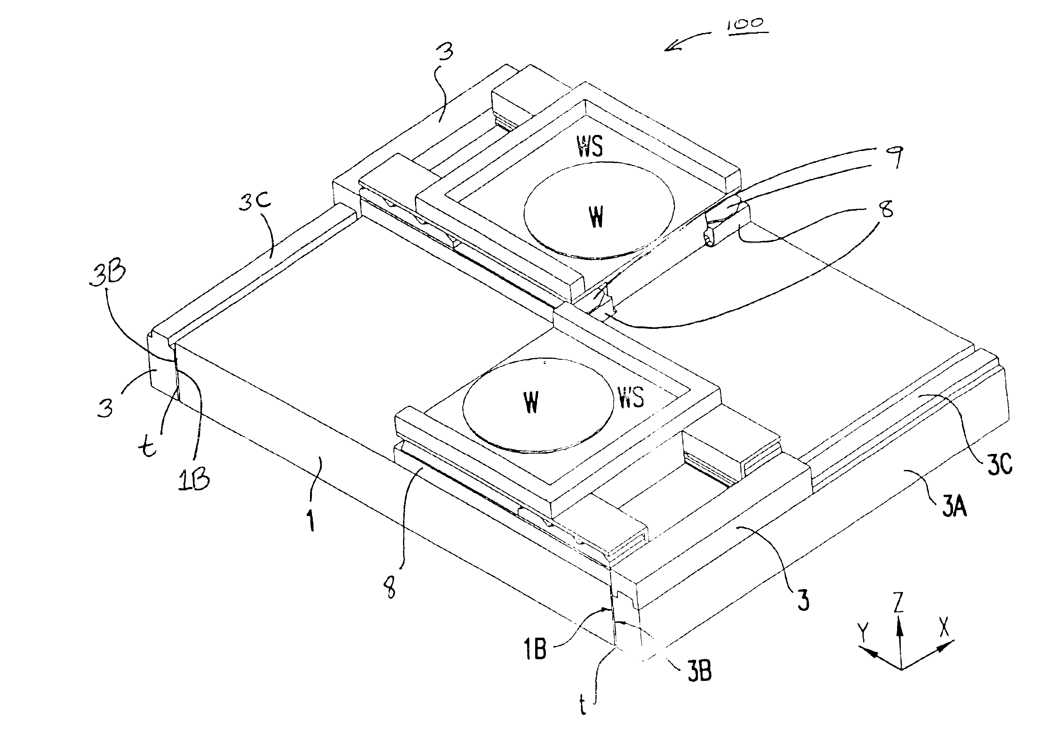
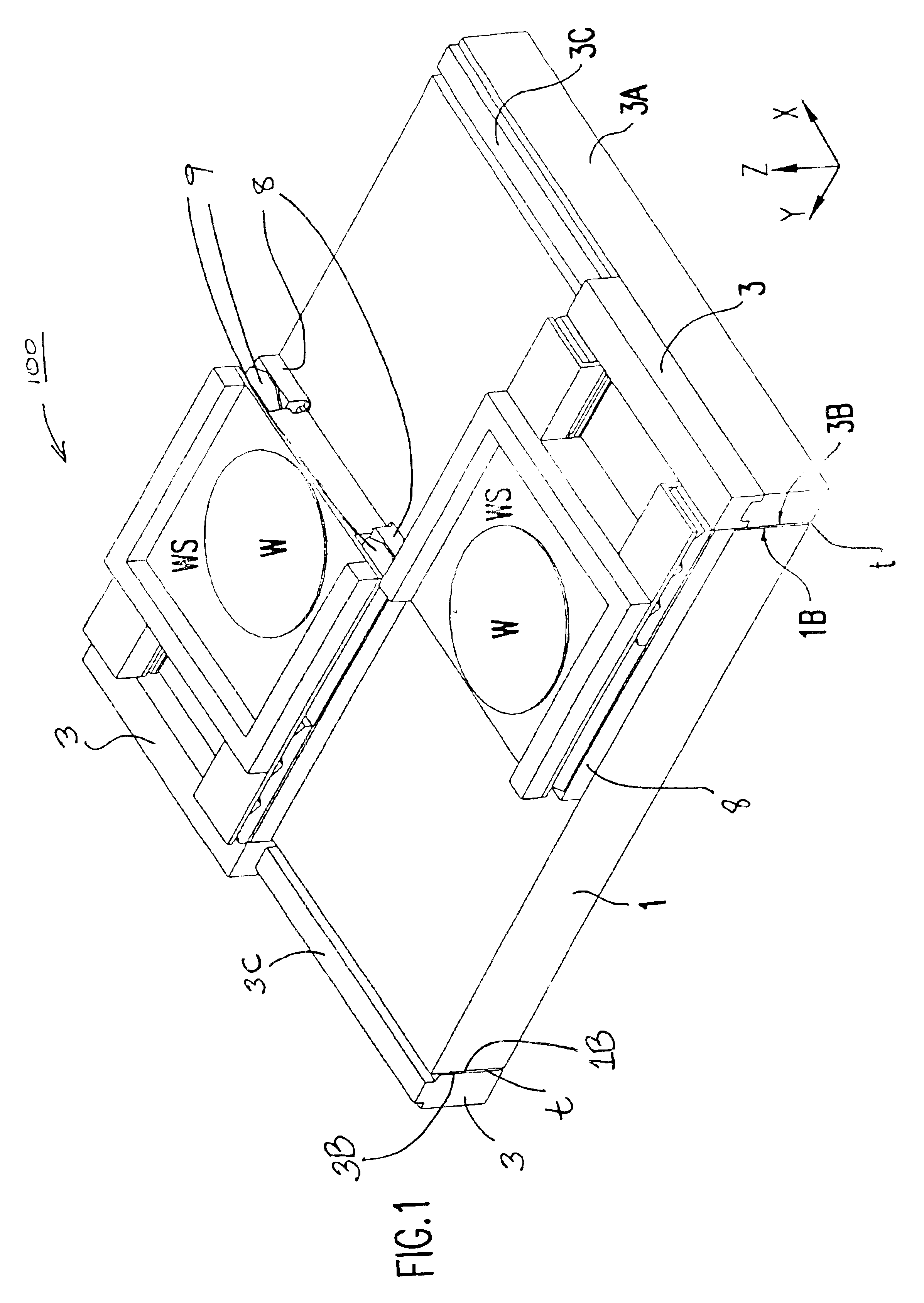
[0033]Referring now to the drawings, and more particularly to FIGS. 1 through 4, a motor assembly of an exemplary form in accordance with a preferred embodiment of the invention is shown. FIGS. 1 through 4 show a moving-magnet embodiment.

[0034]The motor assembly shown in FIG. 1 depicts two wafer stages, WS on each of which is respectively positioned wafer W. As shown in FIGS. 1 and 4, the invention allows a lithography machine to use two wafer stages WS to increase throughput. It will be appreciated that the two wafer stages may be the same or different, and that the number of wafer stages is not required to be two, and may be one, three, four, etc.

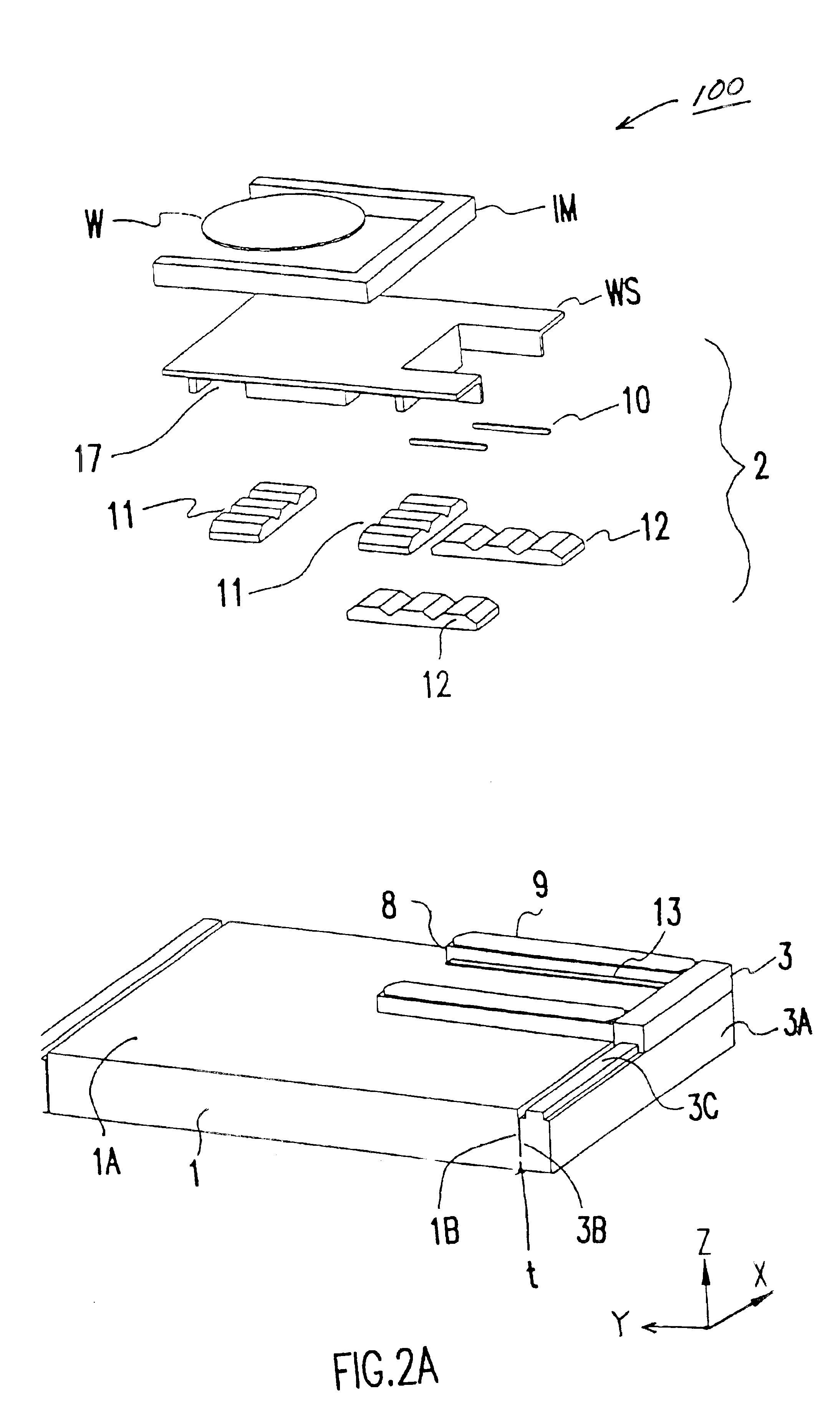
[0035]In FIGS. 1 and 2, a base 1 is provided. The base 1 is suitable for housing a motor that acts between the base 1 and stage WS to move the stage WS in the “x” direction, such as motor 2 in FIG. 2A. (It will be appreciated that x, y and z directions are labeled on the figures and discussed herein for convenience of reference and easy d...


PUM

PropertyMeasurementUnit
of wavelengthaaaaaaaaaa
forceaaaaaaaaaa
lengthaaaaaaaaaa

Abstract

In electric motor assemblies, separating the x and y coils may achieve significant advantages. An advantageous design includes pairs of interacting magnet array / coil arrays. Separated coil arrays are provided, with a coil array on an arm connected to a following stage, and another coil array on a stage base (the stage being one to which is attached magnet arrays). Positioning devices, moving magnet motor assemblies, moving coil motor assemblies, and methods of driving a stage are provided. By differential driving and creation of torques about the x and y axes, a stage may be driven in six independent degrees of freedom.

Description

BACKGROUND OF THE INVENTION[0001]1. Technical Field[0002]This invention relates generally to electric motors and more particularly to two-dimensional electric motors.[0003]2. Background Art[0004]Electric motors are used in a variety of electrical equipment. For example, linear electric motors produce electrical power propelling an armature in one dimension. Wafer stages use linear electric motors to position a wafer during photolithography and other semiconductor processing.[0005]A typical one-dimensional linear electric motor has a magnet track with pairs of opposing magnets facing each other. Within spaces between the pairs of opposing magnets, an armature moves. The armature has windings of a conductor which are connected to an electrical current. When the electrical current is turned on, the electric current interacts with the magnetic fields of the magnet pairs to exert force on the armature, causing the armature to move. When the armature is attached to a wafer stage, the wafe...

Claims


Application Information

Patent Timeline
Patent Type & Authority Patents(United States)
IPC IPC(8): G03F7/20H01L21/67H01L21/68H02K41/02
CPCG03F7/70716G03F7/70733G03F7/70758H01L21/682H02K41/031H02K2201/18
Inventor BINNARD, MICHAELYUAN, BAUSAN
Owner NIKON CORP
Why Eureka
Try Eureka