

Drum type core with discrete structure
a discrete structure and core technology, applied in the direction of cores/yokes, fixed transformers, transformers/react mounting/support/suspension, etc., can solve the problems of critical drawbacks, short-circuit problems, terminals touching the edges at the inside face of the flange portion, etc., to achieve high surface electrical resistance, high permeability and saturation flux density, and small size
- Summary
- Abstract
- Description
- Claims
- Application Information
AI Technical Summary
Benefits of technology
Problems solved by technology
Method used
Image

Examples
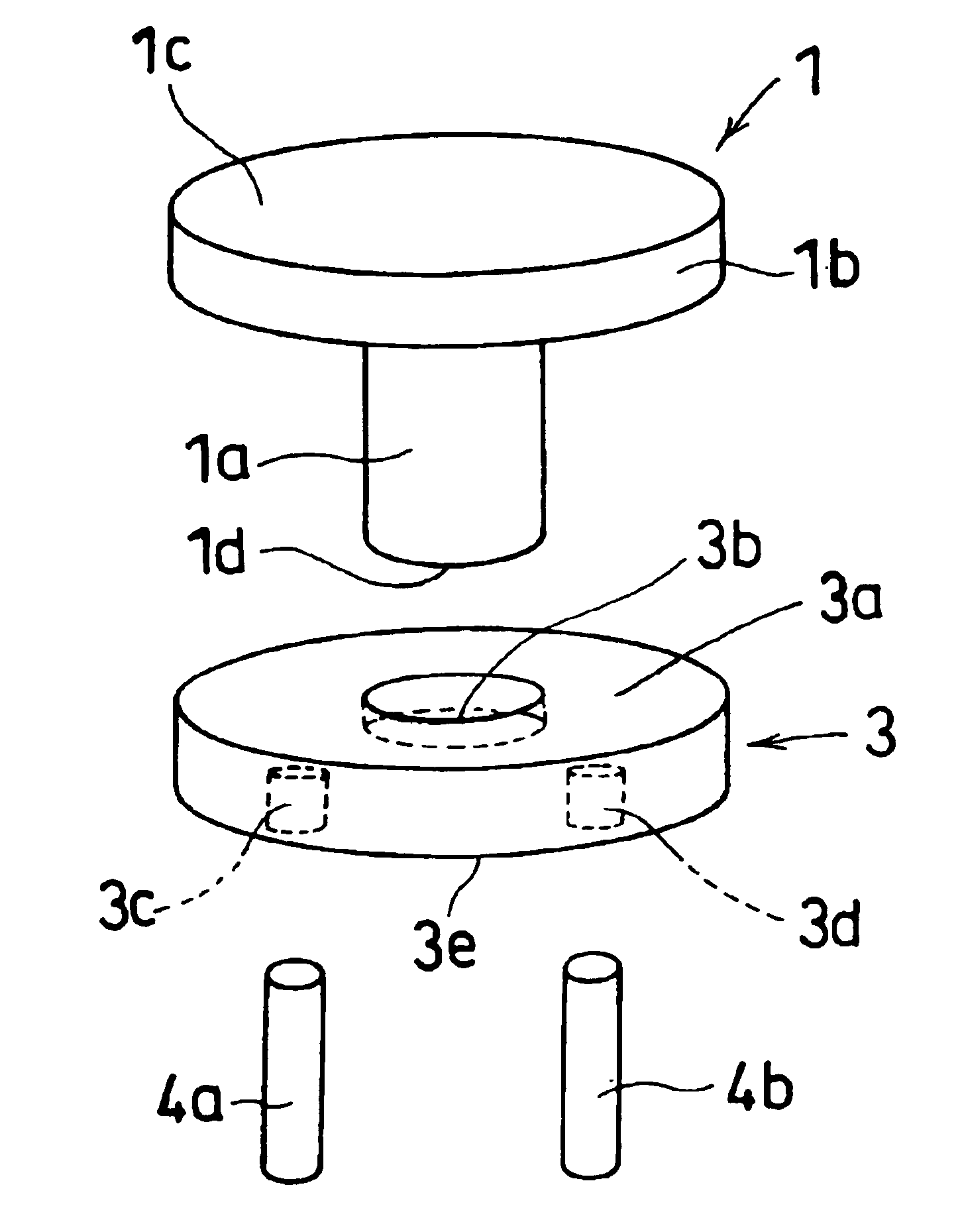
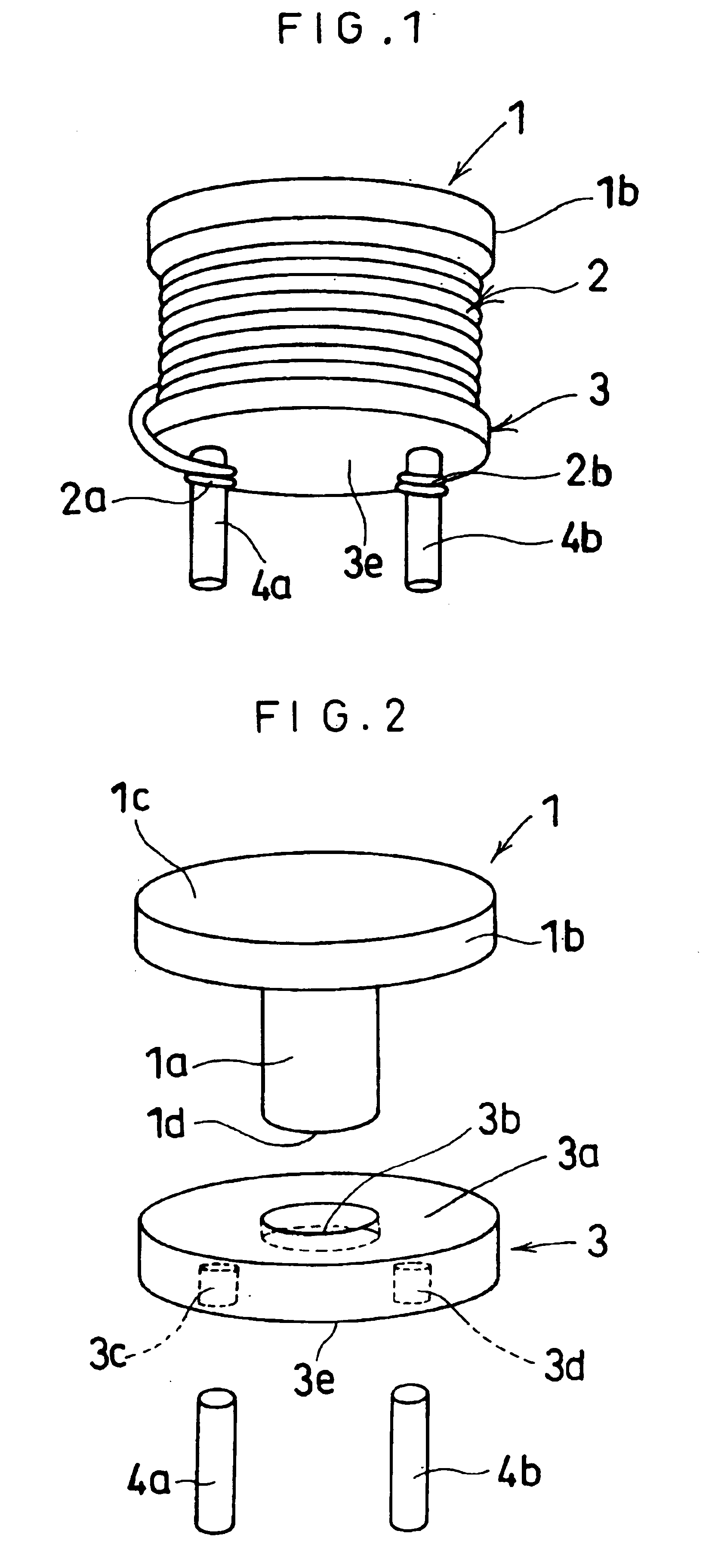
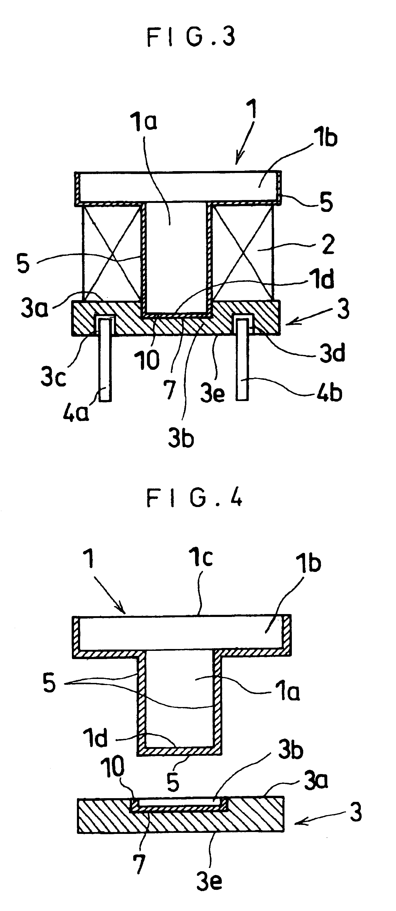
first embodiment
[0040]FIGS. 5 to 7 show further embodiments of the present invention, in which the flanged cylinder 1, the flange piece 3, the epoxy resin 5, and the epoxy resin 10 are identical with those of the first embodiment, and their explanation is omitted.
second embodiment
[0041]Referring to FIG. 5 showing a second embodiment, terminal plates 4c, 4d are attached on an outer side 3e of a flange piece 3 with an adhesive 6. Wire terminals 2a, 2b of a coil 2 pass by the circumference of the flange piece 3 and are bound around the terminal plates 4c, 4d, respectively. With this configuration, the molding die for the flange piece 3 does not involve the holes 3c, 3d, thereby reducing the mold cost, and also decreasing the height of the core to be suitable for surface mounting.
third embodiment
[0042]Referring to FIG. 6 showing a third embodiment, wire terminals 2a, 2b of a coil 2 are taken out immediately from a circumference 3f of a flange piece 3. An adhesive 6 is applied to the circumference 3f so as to fix the wire terminals 2a, 2b.
[0043]The above embodiments shown in FIGS. 5 and 6 are applicable when the wire of the coil 2 is thick, and eliminate the terminal pins 4a, 4b, thereby reducing the cost.
PUM
 Abstract
Description
Claims
Application Information