Al technical title is built by PatSnap Al team. It summarizes the technical point description of the patent document.
a stretcher and long delay technology, applied in the field of long delay and high tis pulse stretchers, can solve the problems of large and complex construction and operation of laser systems comprised of two separate systems, high cost, and high cost of downtime, and achieve the effects of increasing output power, wavelength stability and bandwidth, and pulse energy stability. stability and bandwidth, wavelength stability and bandwidth, and wavelength stability and bandwidth
Inactive Publication Date: 2005-08-09
CYMER INC
View PDF44 Cites 115 Cited by
Summary
Abstract
Description
Claims
Application Information
AI Technical Summary
This helps you quickly interpret patents by identifying the three key elements:
Problems solved by technology
Method used
Benefits of technology
Problems solved by technology
These excimer lasers, when used for integrated circuit lithography, are typically operated in an integrated circuit fabrication line “around-the-clock” producing many thousands of valuable integrated circuits per hour; therefore, down-time can be very expensive.
Laser systems comprised of two separate systems tend to be substantially more expensive, larger and more complicated to build and operate than comparable single chamber laser systems.
Therefore, commercial application of these two chamber laser systems has been limited.
Method used
Image
Click on the blue label to locate the original text in one second.
Reading with bidirectional positioning of images and text.
Examples
Embodiment Construction
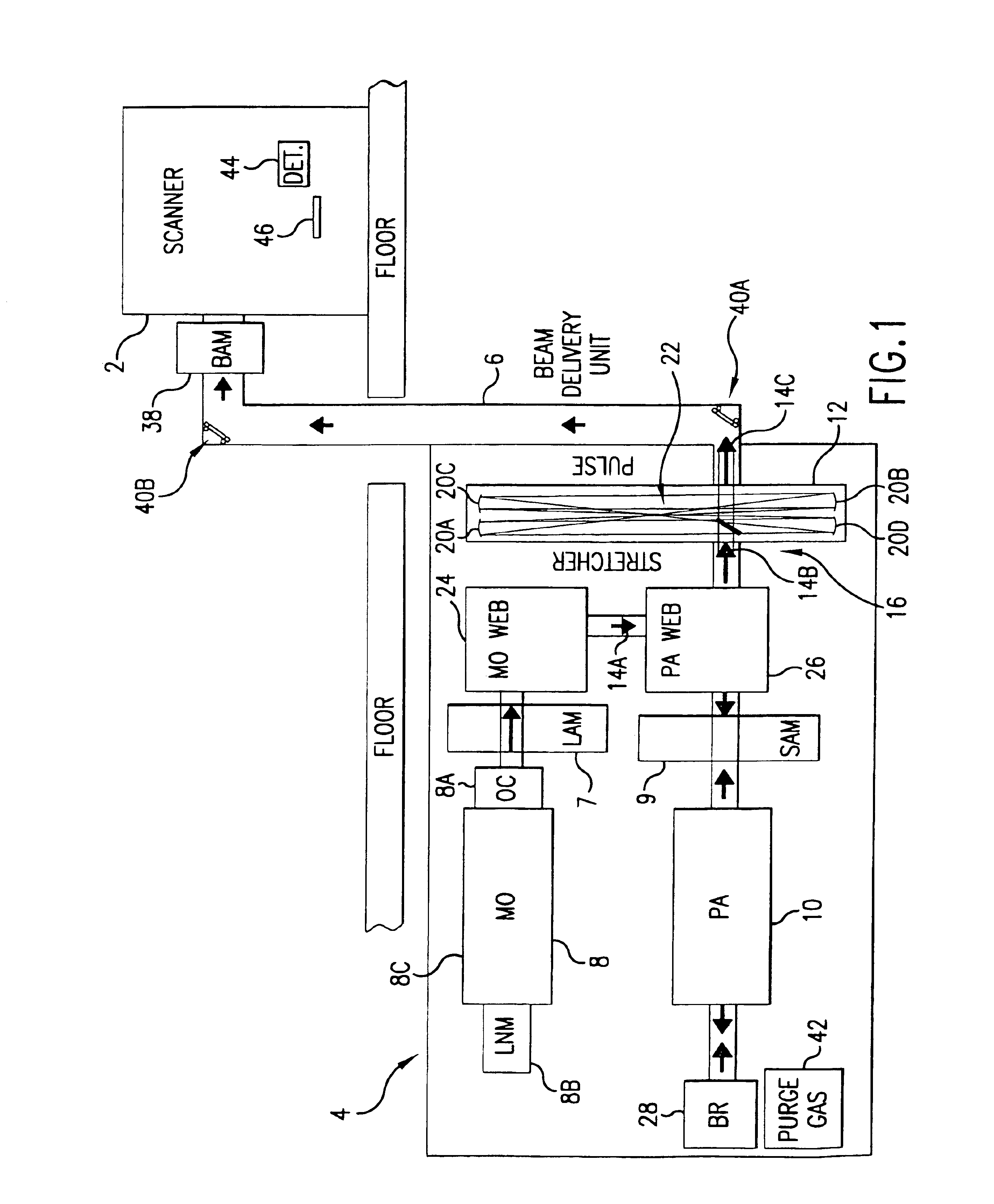
[0034]A first preferred embodiment of the present invention is shown in FIG. 1. In this embodiment a 193 nm ultraviolet laser beam is provided at the input port of a stepper lithography machine 2 such, as the one of those supplied by Canon and Nikon with facilities in Japan and ASML with facilities in the Netherlands. In this case the main components of the laser system 4 are installed below the deck on which the scanner is installed. However, this laser system includes a beam delivery unit 6 which provides an enclosed beam path for delivering the laser beam to the input port of the scanner.
[0035]This particular laser system includes a master oscillator and a power amplifier 10 and is a type of laser system known as MOPA system. This MOPA arrangement represents an important advancement in integrated circuit light sources over the prior art technique of using a single laser oscillator to provide the laser light. The master oscillator and the power amplifier each comprise a discharge ...
PUM
Abstract
A method and apparatus for laser light pulse stretching is disclosed which may comprise a beam splitter in the path of a laser output light pulse beam; selected to pass a first percent of the energy of a first input pulse of the laser output light pulse beam along a laser output light pulse beam output path as a first output pulse and to reflect a second percent of the energy of the laser output light pulse beam into a first delayed beam; an optical delay path receiving the first delayed beam and returning the first delayed beam to the beam splitter in an orientation such that a third percent of the first delayed beam is reflected into the output path as a second output pulse and a fourth percent is passed into the optical delay path as a second delayed beam; the optical delay path receiving the second delayed beam and returning the second delayed beam to the beam splitter in an orientation such that the third percent of the second delayed beam is reflected into the output path as a third output pulse and the fourth percent of the second delayed beam is passed into the optical delay path as a third delayed beam; the optical delay path receiving the third delayed beam and returning the third delayed beam to the beam splitter in an orientation such that the third percent of the third delayed beam is reflected into the output path as a fourth output pulse; the first input pulse being a first pulse in a plurality of pulses output from a prior pulse stretcher, each of a plurality of succeeding input pulses comprising the output of the prior pulse stretcher resulting from the stretching of a narrow band laser light output pulse, forming successive first, second, third and fourth output pulses, the combination of which forms a pulse stretcher having an output with TIS of at least 200 ns. The optical delay path may be formed of a plurality of at least eight reflecting mirrors and contained in an elongated enclosure having first and second end plates mounting a first group of at least four of the at least eight reflecting mirrors mounted on the first mounting surface symmetrically about a center axis of the optical delay path and a second group of at least four of the at least eight reflecting mirrors mounted on the second mounting surface symmetrically about the center axis. The mirrors may be staggered in a predefined pattern, e.g., a circular pattern. The delay path may lie in a plurality of planes. The apparatus may be part of a laser system, part of a beam delivery system or an interface between the two.
Description
[0001]The present invention is a continuation-in-part of Ser. No. 10 / 141,216, filed May 7, 2002 now U.S. Pat. No. 6,693,939 and is incorporated herein by reference.BACKGROUND OF THE INVENTIONElectric Discharge Gas Lasers[0002]Electric discharge gas lasers are well known and have been available since soon after lasers were invented in the 1960s. A high voltage discharge between two electrodes excites a laser gas to produce a gaseous gain medium. A resonance cavity containing the gain medium permits stimulated amplification of light which is then extracted from the cavity in the form of a laser beam. Many of these electric discharge gas lasers are operated in a pulse mode.[0003]U.S. Pat. No. 6,625,191, entitled VERY NARROW BAND, TWO CHAMBER, HIGH REP RATE GAS DISCHARGE LASER SYSTEM, issued to Knowles, et al. on Sep. 23, 2003, U.S. Pat. No. 6,535,531, entitled GAS DISCHARGE LASER WITH PULSE MULTIPLIER, issued to Smith, et al. on Mar. 18, 2003, U.S. Pat. No. 6,314,119, entitled EXCIMER ...
Claims
Application Information
Patent Timeline
Application Date:The date an application was filed.
Publication Date:The date a patent or application was officially published.
First Publication Date:The earliest publication date of a patent with the same application number.
Issue Date:Publication date of the patent grant document.
PCT Entry Date:The Entry date of PCT National Phase.
Estimated Expiry Date:The statutory expiry date of a patent right according to the Patent Law, and it is the longest term of protection that the patent right can achieve without the termination of the patent right due to other reasons(Term extension factor has been taken into account ).
Invalid Date:Actual expiry date is based on effective date or publication date of legal transaction data of invalid patent.