Use of overlay diagnostics for enhanced automatic process control
a technology of automatic process control and overlay, applied in the direction of semiconductor/solid-state device testing/measurement, instruments, photomechanical equipment, etc., can solve the problems of affecting overlay measurement, affecting overlay measurement, and reporting overlay results that are not reliabl
- Summary
- Abstract
- Description
- Claims
- Application Information
AI Technical Summary
Benefits of technology
Problems solved by technology
Method used
Image
Examples
first embodiment
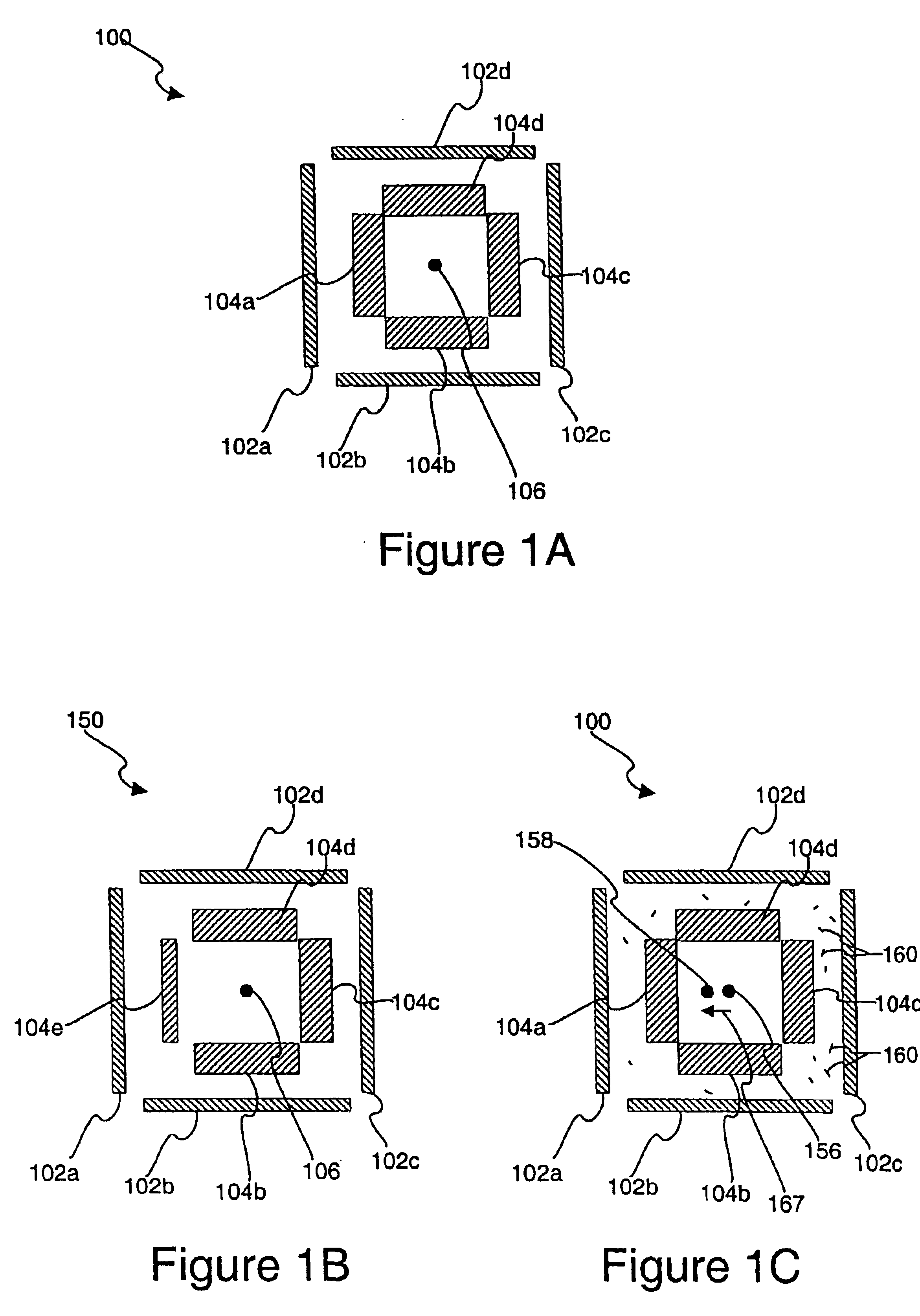
[0060]Any suitable techniques may be used to calculate a confidence level for the target overlay data based on the provided systematic and / or noise metrics. FIG. 5 is a flowchart illustrating a procedure 500 for determining the confidence level of particular overlay data in accordance with the present invention. Initially, a set of calibration wafers are run in operation 502. The weight values for the target diagnostic metric are estimated from the data in operation 504. The data is generally raw overlay and metrics values. The product wafers are then run in operation 506. A total target uncertainty (TTU) is then calculated for the current target in operation 508. TTU is defined as, for example, the target of FIGS. 1A˜1C or FIG. 3B: TTU=A*AsymmetryInnerX+AsymmetryInnerY2+B*AsymmetryOuterX+AsymmetryOuterY2+C*(NoiseMetricX)2+(NoiseMetricY)22
where A, B, and C are weights. The units may be any unit of measurement, such as nm.
[0061]After the TTU value is determined, it is then determi...
second embodiment
[0062]FIG. 6 is a flowchart illustrating a procedure 600 for determining a confidence level in accordance with the present invention. The operations 602-606 are similar to the operations 502-506 of FIG. 5. However, in this embodiment a relative target uncertainty (RTU) value is calculated for the current target in operation 608. In this embodiment, the confidence level result is relative to the overlay budget or some other variable, and translated to a relative notation, such as a %. RTU may be defined relative to the TTU value and a Reference Value as: RTU=(1-TTUReferenceValue)*100%
[0063]The Reference Value is generally determined by the overlay budget or some other representative process value. After the RTU value is determined, it is then determined whether the RTU value is less than a predetermined threshold in operation 610. If the RTU is not less than the threshold, the target is good in operation 614. If the RTU is less than the threshold, the target is a flyer in operation ...
fourth embodiment
[0067]FIG. 8 is a flowchart illustrating a procedure 800 for determining a confidence level with the present invention. In general terms, this technique is based on the relative accuracy of the current target metric with respect to calibration data. Calibration wafers (lot, set of lots) are run and means of the metrics are calculated. Then for the current run, the relative accuracy of the metric is calculated. And at the final step, the results are added to the calibration data and means are recalculated.
[0068]Initially, a set of calibration wafers are run in operation 802, and the means of the metrics for the calibration wafers are then calculated in operation 803. The weights are then estimated based on the data in operation 804. A set of product wafers are then run in operation 806. A calibration relative confidence level (CRCL) value is then calculated for the current target in operation 808. The CRCL may be defined as for example, the target of FIGS. 1A˜1C or FIG. 3B as: CRCL=...
PUM
 Abstract
Description
Claims
Application Information
 - R&D
- Intellectual Property
- Life Sciences
- Materials
- Tech Scout
- Unparalleled Data Quality
- Higher Quality Content
- 60% Fewer Hallucinations
Browse by: Latest US Patents, China's latest patents, Technical Efficacy Thesaurus, Application Domain, Technology Topic, Popular Technical Reports.
© 2025 PatSnap. All rights reserved.Legal|Privacy policy|Modern Slavery Act Transparency Statement|Sitemap|About US| Contact US: help@patsnap.com


