Eureka AIR delivers breakthrough ideas for toughest innovation challenges, trusted by R&D personnel around the world.

Electro-hydraulic manifold assembly with lead frame mounted pressure sensors

Active Publication Date: 2005-08-16
EATON CORP
View PDF6 Cites 22 Cited by
  • Summary
  • Abstract
  • Description
  • Claims
  • Application Information

AI Technical Summary

Benefits of technology

[0005]The present invention thus permits individual connection of the electrical leads to the solenoid operated valves and installation of the pressure transducers in one operation when the lead frame is attached to the manifold block.

Problems solved by technology

However, in providing the pressure sensors at each electric valve outlet for generating an electrical signal indicative of the shift clutch actuating pressure, it has been found disadvantageous from an assembly complexity, size and cost standpoint to provide individual electrical leads to the plurality of sensors and electrically operated valves on the manifold.
This has been found to require a prohibitive large space for access to the terminals and the wiring harness within the transmission casing for the manifold assembly.

Method used


Image

  • Electro-hydraulic manifold assembly with lead frame mounted pressure sensors
  • Electro-hydraulic manifold assembly with lead frame mounted pressure sensors
  • Electro-hydraulic manifold assembly with lead frame mounted pressure sensors

Examples


Embodiment Construction

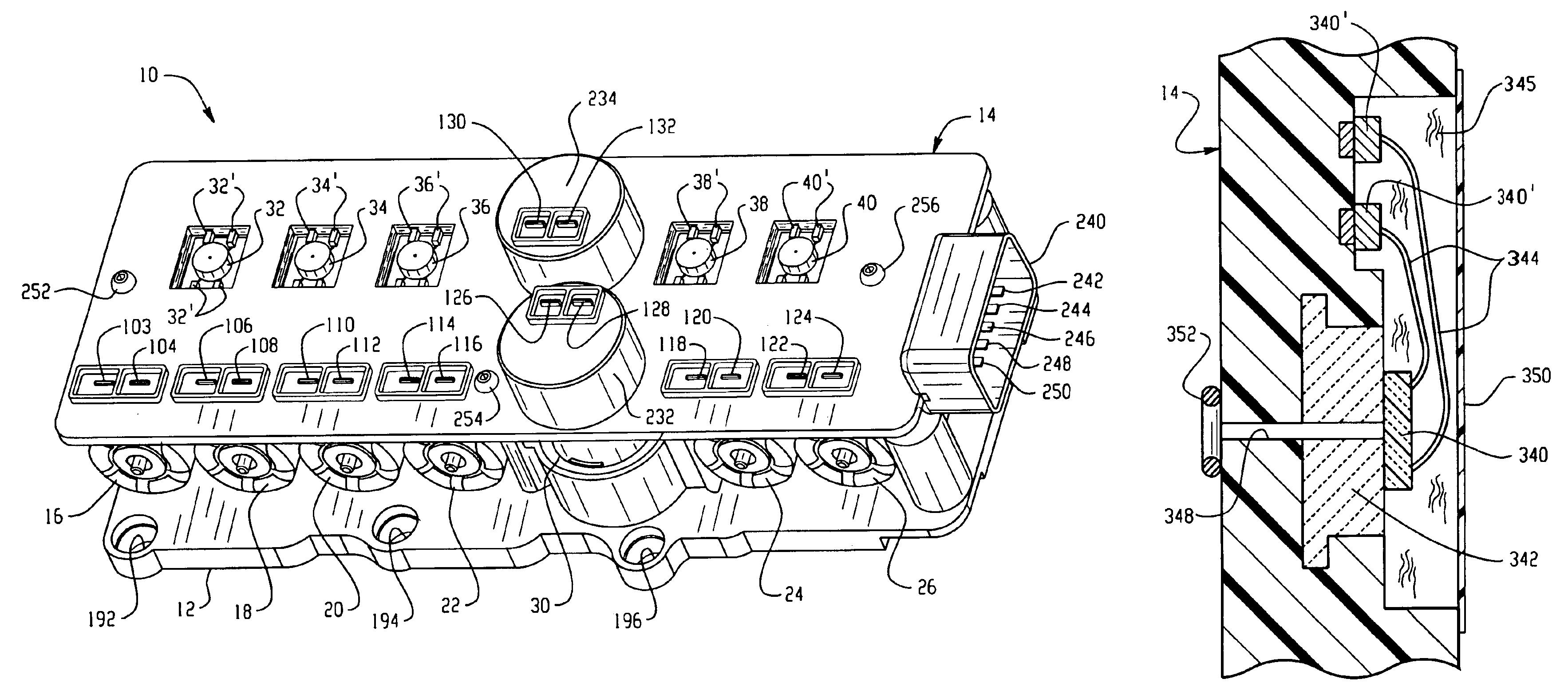
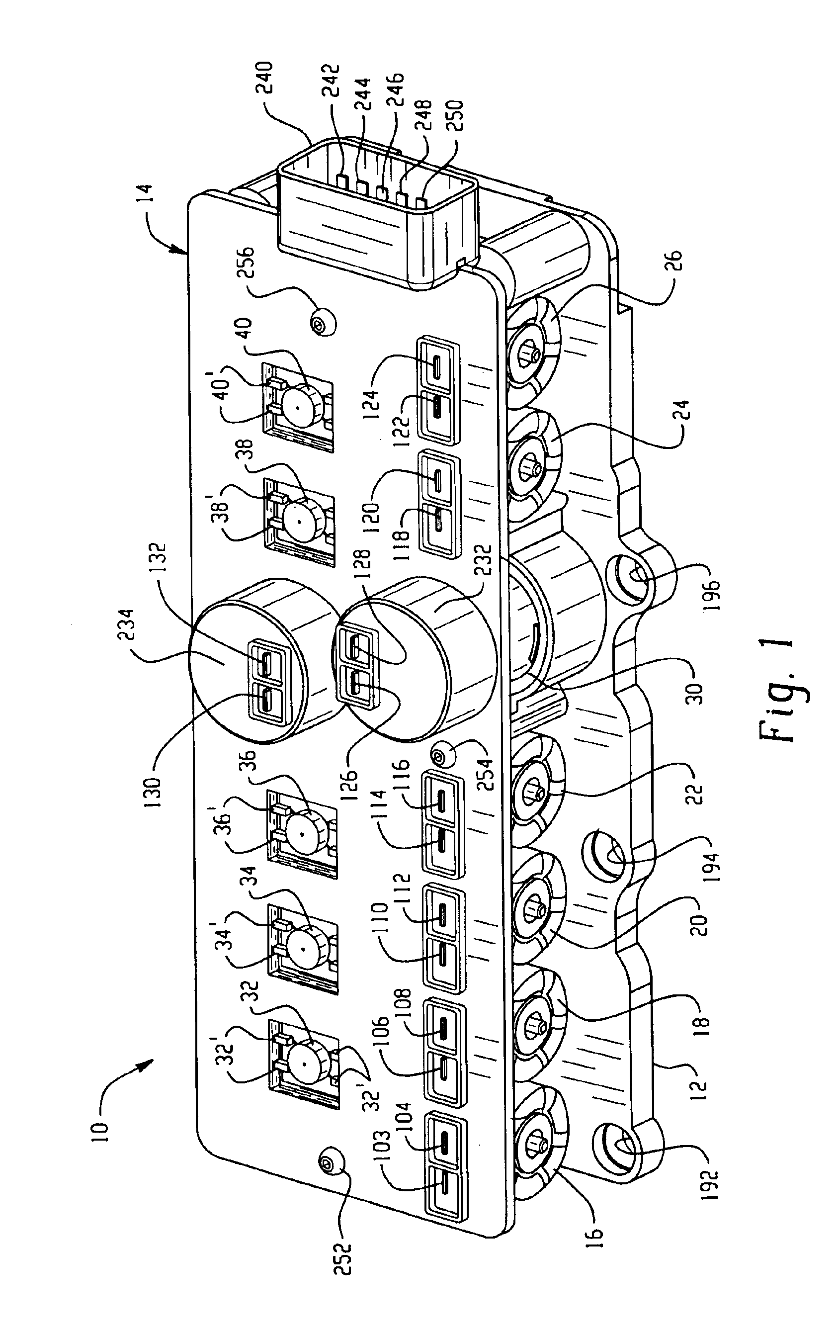
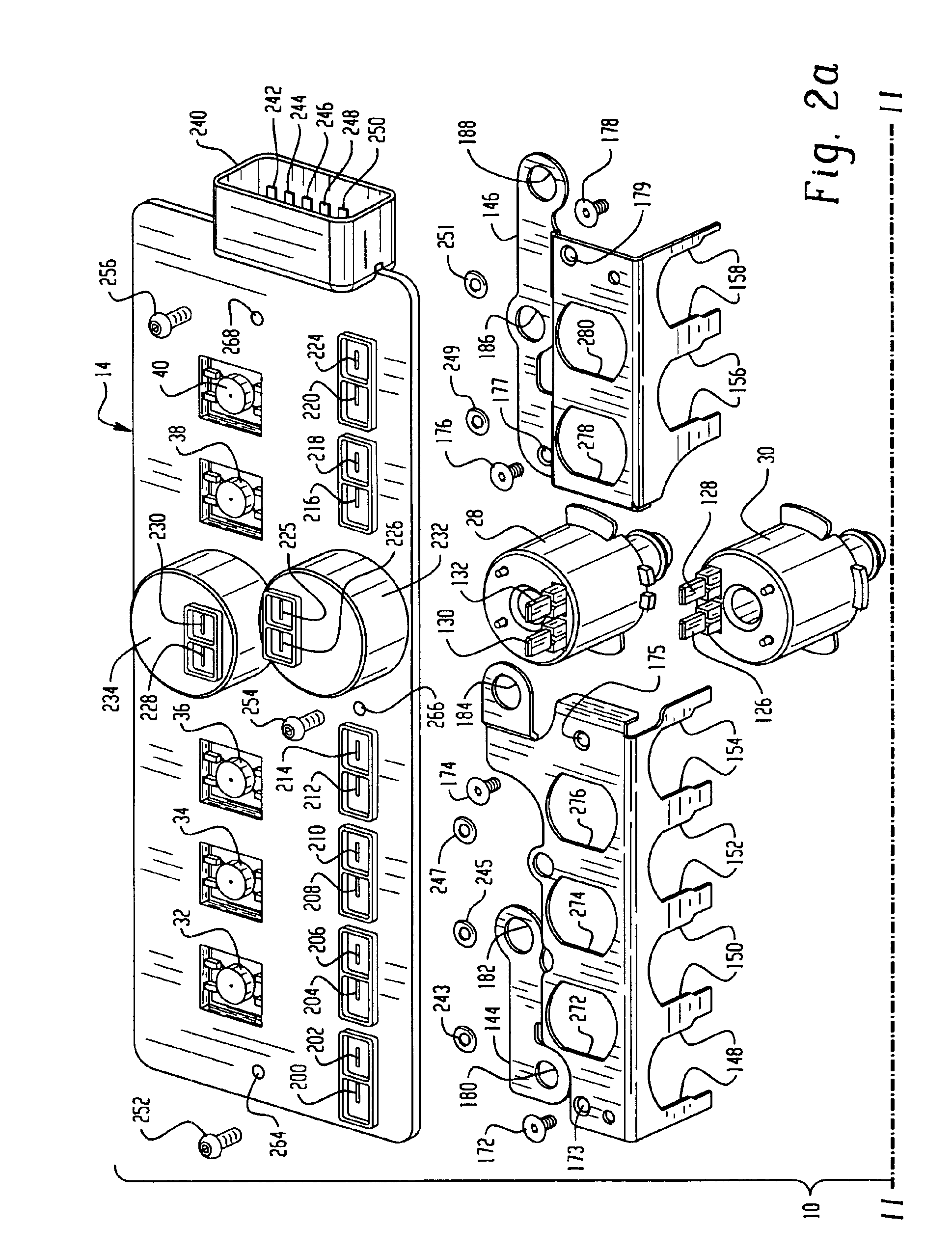
[0013]Referring to FIGS. 1 through 5, an embodiment of the invention is indicated generally at 10 and includes a manifold block 12, an electrical lead frame assembly indicated generally at 14 and a plurality of solenoid operated valves 16,18, 20, 22, 24, 26, 28, 30.

[0014]The lead frame assembly 14 includes a plurality of pressure sensors or transducers 32, 34, 36, 38, 40, each having leads secured or attached to electrically conductive pads denoted respectively by the primed reference numeral for each of the transducers.

[0015]The manifold block 12 has a plurality of valving cavities 42, 44, 46, 48, 50, 52, formed horizontally in the vertically extending side 54 of the manifold block 12, with each of the valving cavities having an outlet passage denoted respectively 56, 58, 60, 62, 64, 66 which are connected (not shown) to the underside of the block and are adapted to connect with corresponding hydraulic passages in the device to be controlled such as the control pressure passages in...


PUM


Abstract

An electro-hydraulic manifold assembly with a plurality of solenoid operated valves disposed on a manifold block and each operable to control pressure from the inlet to a separate outlet. Sensing ports are provided in each outlet with a pressure sensor sealed over the sensing port for providing a signal indicative of the sensed pressure. The pressure sensors are mounted on a lead frame and connected to conductive strips in the lead frame. The lead frame has slots therein which permit the frame to be simultaneously electrically connected by bayonet connection to the terminals on each solenoid valve as the transducers are sealed over the sensing ports and the lead frame attached to the manifold block.

Description

BACKGROUND OF THE INVENTION[0001]The present invention relates to manifold assemblies of the type having an hydraulic fluid pressure inlet communicating with a plurality of valve chambers, each having an electrically operated valve ported therein for controlling, upon energization, fluid pressure selectively to individual outlets for the respective valving chambers. Manifolds of this type are employed for controlling pressure of hydraulic fluid in servo-actuators as, for example, clutch actuators in automatic speed-change power transmissions for motor vehicles where it is desired to control the speed change or shifting patterns of the transmission with an electronic controller. This arrangement has found widespread use in modern vehicle automatic transmissions because the electronic controller can receive in real time multiple inputs of vehicle operating parameters such as road speed, throttle position and engine RPM; and, the electronic controller can be programmed to provide optim...

Claims


Application Information

Patent Timeline
IPC IPC(8): F16H61/00F15B13/044G05D16/20
CPCF16H61/0009F16H2059/683Y10T137/87885A47L9/242F16L11/1185
Inventor FORD, GREG E.GREEN, TIMOTHY J.HERBERT, DAVID E.BOWMAN, HAROLD L.JACOBSEN, PETER M.
Owner EATON CORP
Why Eureka
Eureka Blog
Learn More