Rotary feed-through

a technology of rotary feed-through and rotary cylinder, which is applied in the direction of engine lubrication, instruments, large fixed members, etc., can solve the problems of escape of cooling lubricant, and achieve the effect of optimal sealing

Inactive Publication Date: 2005-08-16
OTT JAKOB & SPANNTECHN
View PDF13 Cites 24 Cited by
  • Summary
  • Abstract
  • Description
  • Claims
  • Application Information

AI Technical Summary

Benefits of technology

[0008]The object of the invention is to create a rotary feed-through of the type mentioned in the introduction, which has a simpler construction and in addition to low wear and tear, also exhibits lower leakage losses both with the supply of cooling lubricant and also with the supply of compressed air.
[0010]For the rotary feed-through according to the invention, the sliding surfaces are also in contact when the supply of cooling lubricant or compressed air is switched. This prevents the creation of a gap between the sliding surfaces when the cooling lubricant supply is switched. Such a gap could lead to the escape of cooling lubricant still located in the supply line. A force is applied to the non-rotating sliding bushing in the direction of the hollow shaft so that its sliding surface is constantly pressed against the sliding surface of the hollow shaft. An additional axial load does not result with the supply of compressed air by radial introduction at the sliding bushing, which load would lead to greater contact pressure of the sliding bushing on the sliding surface of the hollow shaft. Only with the supply of cooling lubricant is the contact pressure increased in order to achieve an optimal seal.

Problems solved by technology

Such a gap could lead to the escape of cooling lubricant still located in the supply line.

Method used


Image

  • Rotary feed-through
  • Rotary feed-through
  • Rotary feed-through

Examples


Embodiment Construction

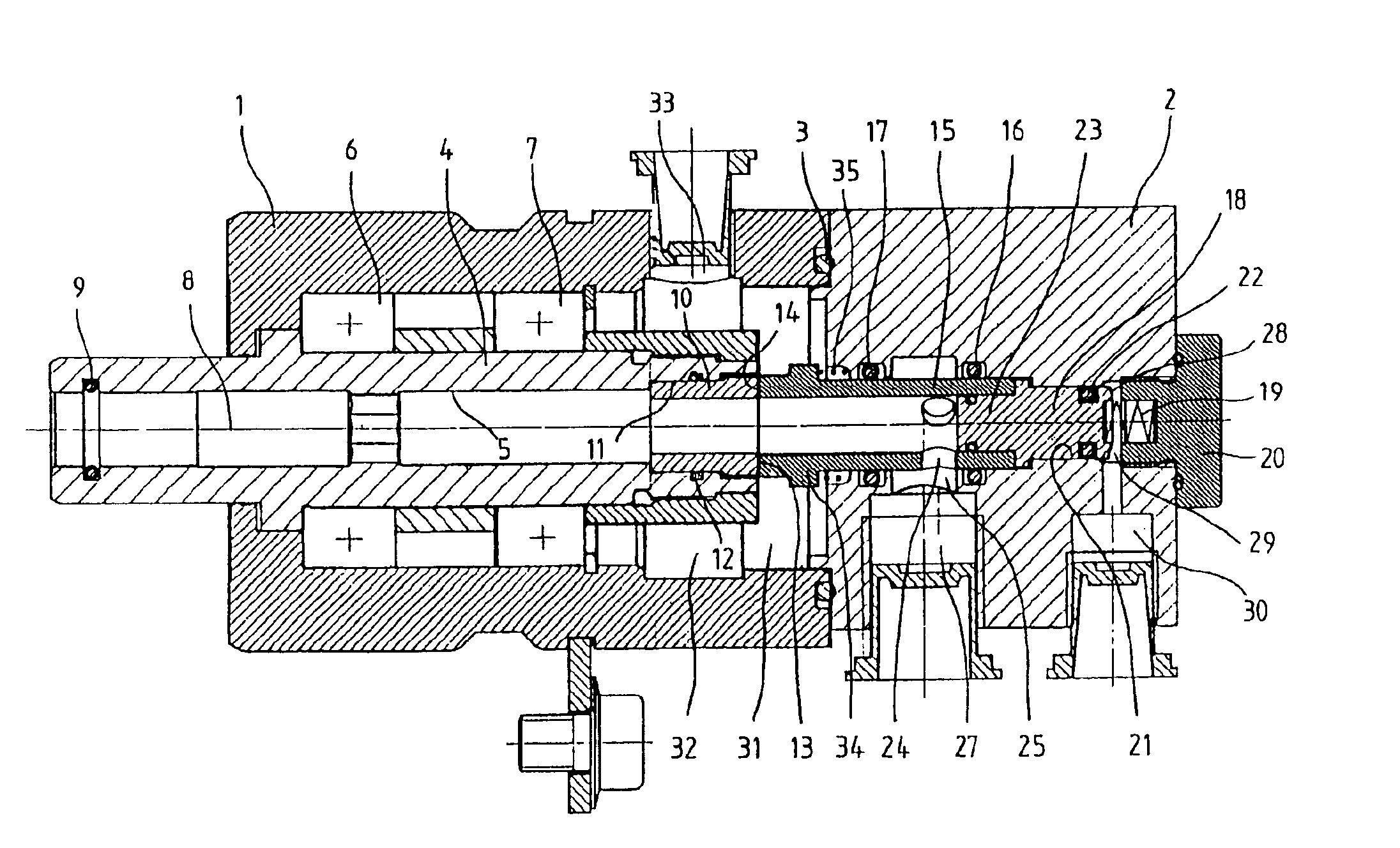
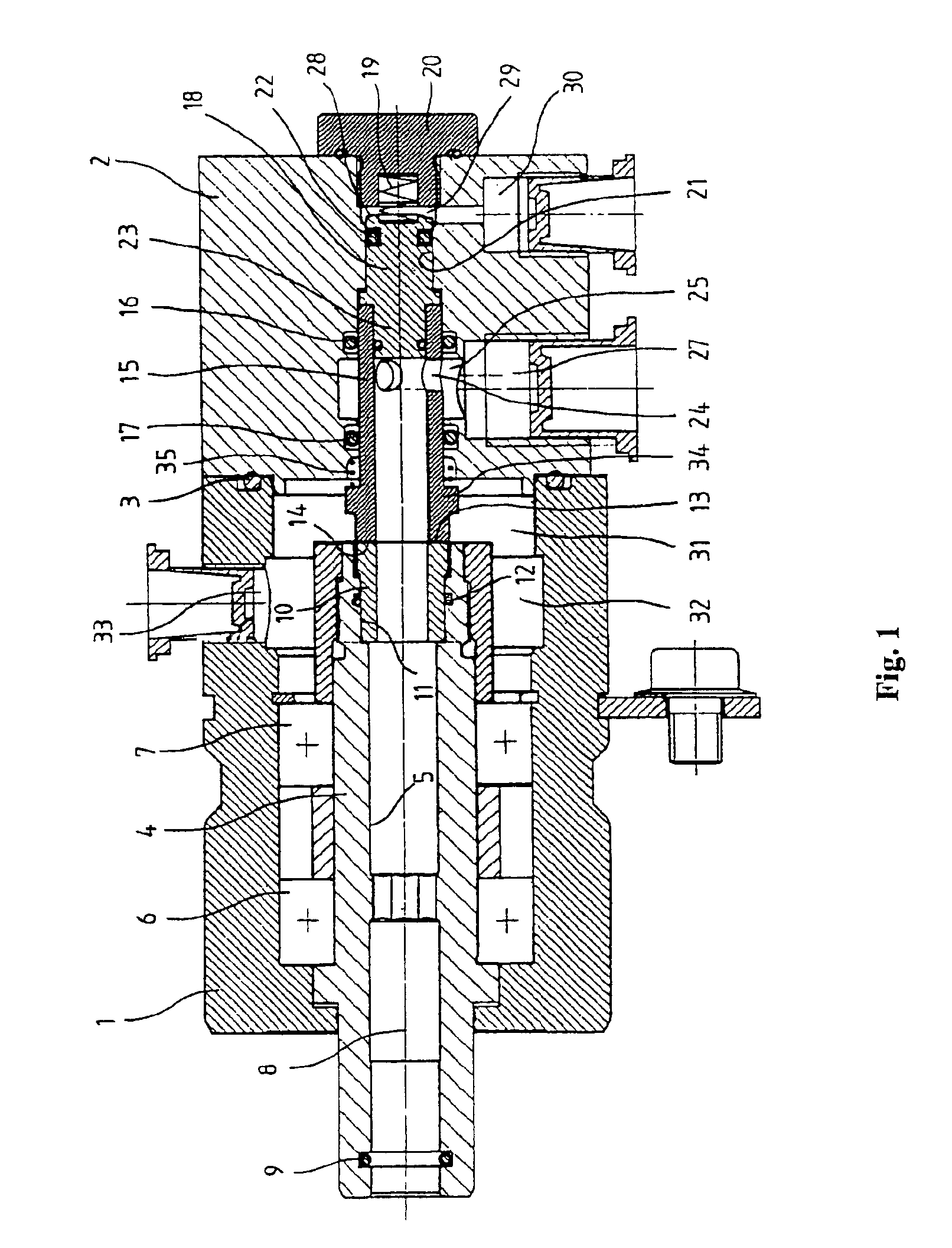
[0014]The rotary feed-through shown in FIG. 1 contains a housing with a front housing part 1 and a rear housing part 2 which is configured as a connecting piece. These parts are connected in a sealed manner to each other by a sealing ring 3. A hollow shaft 4 with a central passage channel 5 is mounted in the front housing part 1 so that the shaft can rotate about a center axis 8 by means of a front and rear rotary bearing 6 and 7, respectively. At the front end of the hollow shaft 4, e.g., a hollow tie rod of a machine tool working spindle is inserted into the passage channel 5 sealed by a sealing ring 9. At the rear end of the hollow shaft 4, there is a first sealing sleeve 10, which is connected rotationally fixed to and which rotates with this shaft. This is inserted into an expanded part 11 of the passage channel 5 at the rear end of the hollow shaft 4 and is sealed by a radial seal 12. The sealing sleeve 10 features a rear end sealing surface 13, which contacts a front end seal...


PUM

PropertyMeasurementUnit
contact pressureaaaaaaaaaa
forceaaaaaaaaaa
temperatureaaaaaaaaaa

Abstract

A rotary feed-through, which contains a hollow shaft, which is supported in a first housing part so that it can rotate, with a first sealing surface and a sealing bushing, which is arranged rotationally fixed within a second housing part and which is coaxial with the hollow shaft, with a second sealing surface for contact to the first sealing surface. In order to also enable lower leakage losses, in addition to less wear, with the supply of cooling lubricants and compressed air, the second housing part contains a first lateral supply channel, which can be attached to a coolant supply line or a compressed air supply line, for the supply of cooling lubricant or compressed air via at least one radial opening of the sealing bushing and a second supply channel, which is charged during the supply of cooling lubricant, for the supply of cooling lubricant to a pressure piston, which closes the rear end of the sealing bushing, to increase the contact pressure of the sealing surfaces.

Description

RELATED APPLICATION[0001]This application is a continuation of International Application PCT / EP03 / 05881 filed Jun. 4, 2003, the contents of which are here incorporated by reference in their entirety, and priority is claimed therefor under 35 USC 120.BACKGROUND OF THE INVENTION[0002]1. Field of Invention[0003]The invention relates to a rotary feed-through.[0004]2. Prior Art[0005]Such rotary feed-throughs are used to supply fluid to a rotating machine part. In particular, with machine tools, such rotary feed-throughs are used to feed a cooling lubricant into a hollow working spindle of the machine tool for cooling or cleaning tools and / or the work point. For typical rotary feed-throughs, the interface between the rotating and the stationary part is formed by sealed bushings or sealing rings with sealing surfaces sliding one on top of the other. For the supply of a lubricant medium, such as, e.g., cooling lubricant, the sealing gap between the two sliding surfaces is lubricated, which ...

Claims


Application Information

Patent Timeline
Patent Type & Authority Patents(United States)
IPC IPC(8): F16L27/08F16L27/00F16L27/093
CPCF16L27/082F16L27/0828Y10T409/304032Y10T137/2559
Inventor JAKOB, LUDWIGGREIF, JOSEFBECHTELER, WOLFGANG
Owner OTT JAKOB & SPANNTECHN
Why Eureka
Try Eureka