Non-jamming, fail safe flight control system with non-symmetric load alleviation capability

a flight control system and non-symmetric technology, applied in the direction of control initiation means, aircraft power plants, without power amplication, etc., can solve the problems of large force, inability to perform, and failure mode causing the surface to be jammed can have catastrophic consequences

Inactive Publication Date: 2005-08-16
DJURIC MIHAILO P
View PDF24 Cites 9 Cited by
  • Summary
  • Abstract
  • Description
  • Claims
  • Application Information

AI Technical Summary

Benefits of technology

[0009]The primary object of this invention is to provide a non-jamming flight control system by which either pilot can continue to control the aircraft despite jamming of one side with no extra effort, no delay in action and no threat of over-controlling the aircraft as a result of jamming.
[0012]Additional benefit of the invention is that it may provide an automatic force balance between the two surfaces in case that a gust, a maneuver, a side slip or a wake produces a higher load on one of the surfaces, whereby the higher loaded surface will decrease while the other side will increase the deflection so that a balance is restored without requiring pilot intervention. This feature may especially be useful in case of the aileron control system by increasing the rolling stability of the aircraft. An installation of a spring or springs within said driving system, as explained latter, may moderate or eliminate this feature if desired by selecting appropriate spring stiffness.
[0015]Yet another benefit of the invention is that, in case of an elevator control system, a dual control system does not necessarily have to be carried throughout the length of the fuselage, but only through an area where a possibility of damage to the controls may exist, for example throughout the engine rotor burst area, offering a possibility of some weight savings.
[0019]Alternately, an electrical gust lock option comprising a polarized solenoid operated pin, a gust lock switch and a source of direct current, all connected in an electric circuit so that when said switch is commanded to a lock position said solenoid extends the pin into a hole provided in said pulley thus locking the control system. Once the system is locked power may be cut off. Moving said gust lock switch to unlock position would supply the power to said solenoid with reversed polarity thus causing said pin to retract and free the control system.

Problems solved by technology

It has been well recognized throughout the aircraft industry that, especially in the actuation of primary flight control surfaces, a failure mode causing the surface to be jammed can have catastrophic consequences.
However, it requires a large force to do it.
First, he tries to control the aircraft but soon realizes he cannot.
Second, he suspects a control jam but does not know which side may be jammed.
Third, he pulls hard on control column trying to activate a disconnect from his side but still nothing happens.
He may also face a possibility of dynamic over-control because of a sudden release of force following the disconnect.
All these designs have a common problem requiring an extra pilot effort, a delay in controlling and possible over-control of the aircraft in a dynamic action following the pin shear or a disconnect.
In a critical phase of flight these problems may cause unpredicted consequences.
Another drawback of many such designs is that it is irreversible during the flight; once the shear pin is sheared or disconnect is achieved the system cannot be converted back to the original configuration until landing and then resetting the system.

Method used


Image

  • Non-jamming, fail safe flight control system with non-symmetric load alleviation capability
  • Non-jamming, fail safe flight control system with non-symmetric load alleviation capability
  • Non-jamming, fail safe flight control system with non-symmetric load alleviation capability

Examples


Embodiment Construction

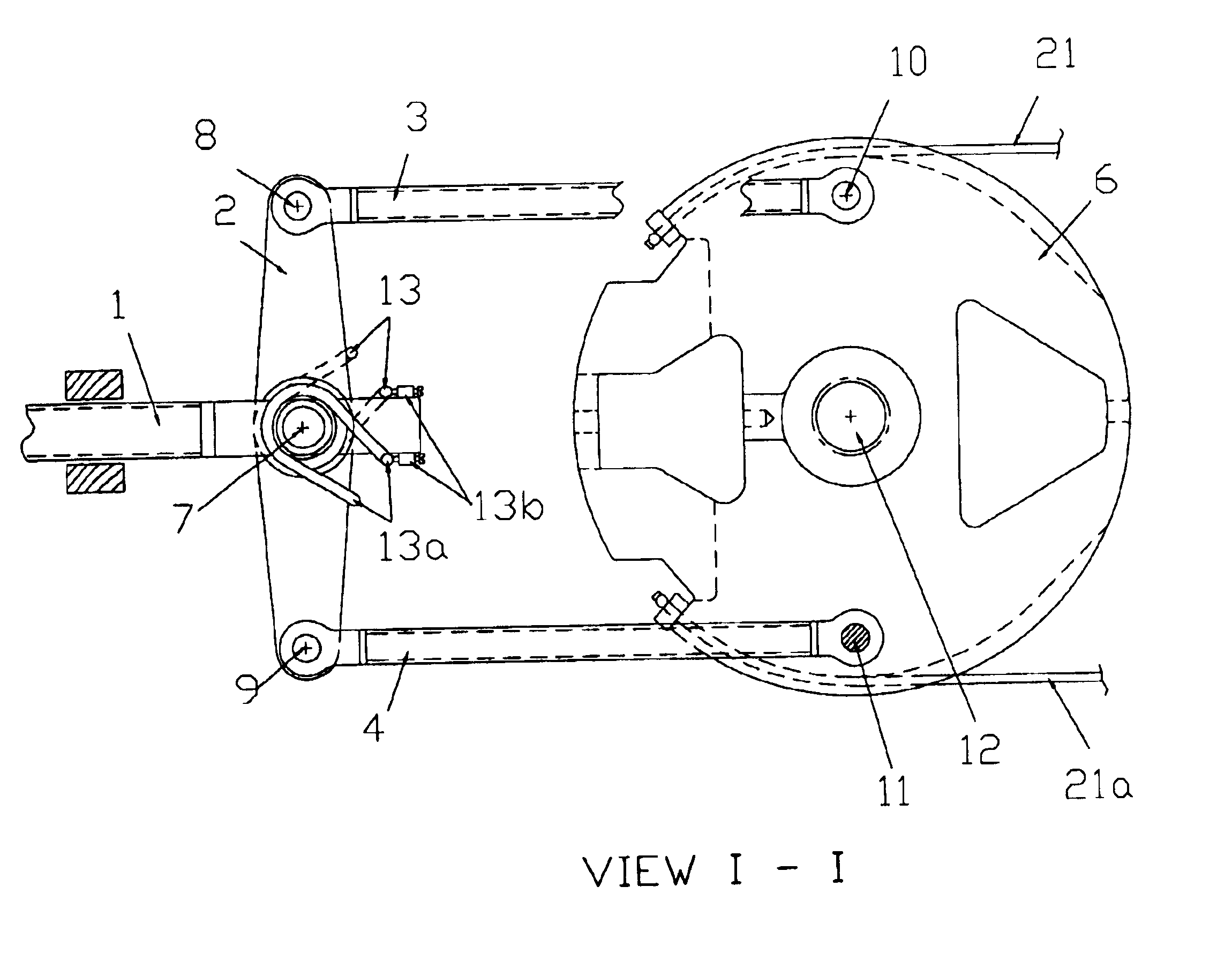
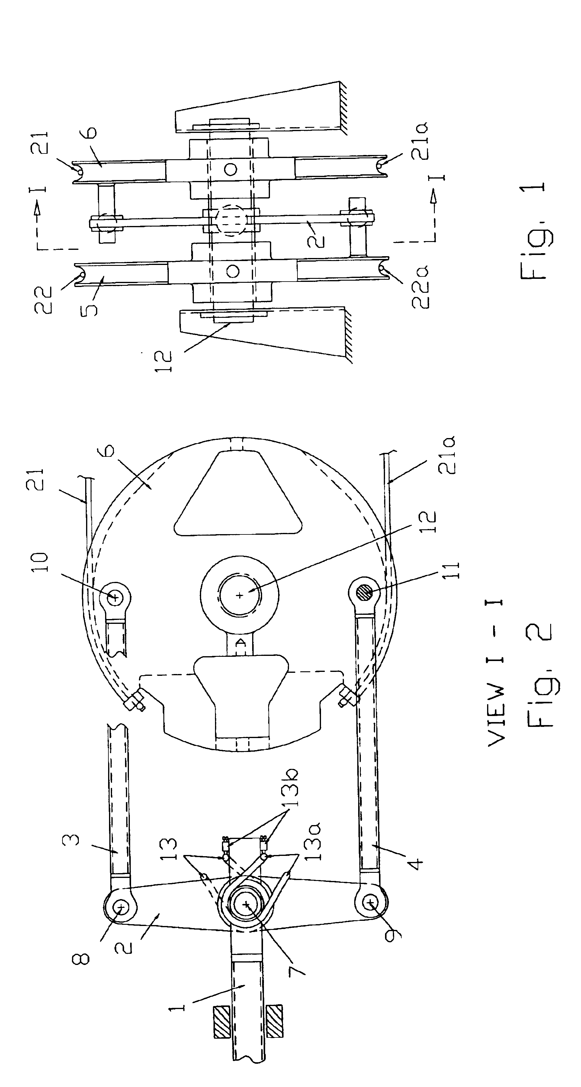
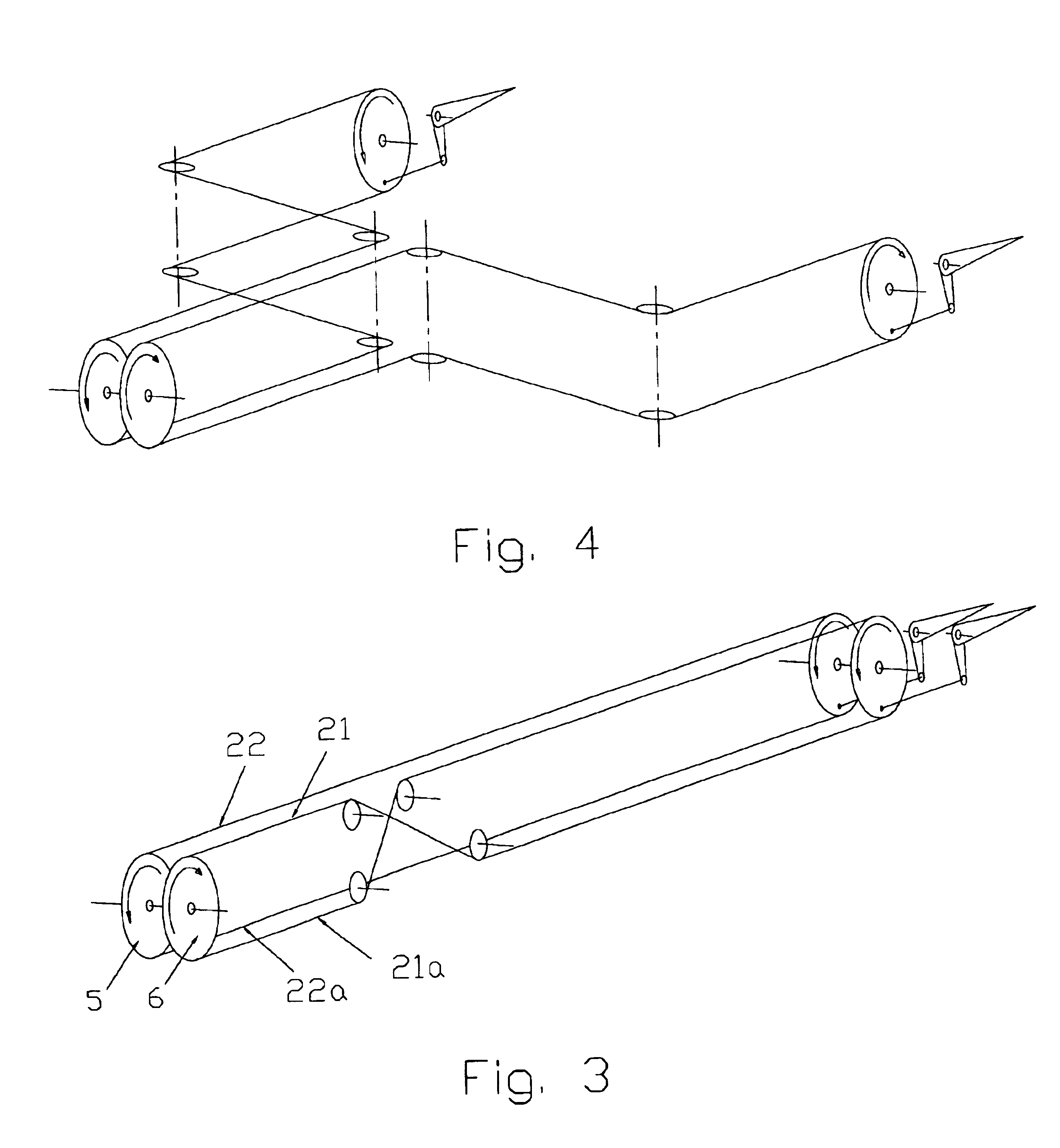
[0033]A preferred driving system shown in FIG. 2 includes at least elements 1 thru 4. When said control input (for example the pilot / copilot flight control load input) is imparted on axially movable element 1 of said driving system, said two-arm bellcrank 2 and said output members—the rod links 3 and 4—operate said pulleys 5 and 6 causing them to rotate about said axle 12. Joints 7 thru 11 are pivotal joints. Each pulley 5 and 6 being coaxial but independently rotatable about said axle 12—by means of control cables 21, 21a, 22 and 22a operates one control surface, for example, the elevator left or right control surface as schematically shown in FIG. 3, even though the invention is equally applicable to the operation of the aileron control surfaces as well. Furthermore, irrespective of the pilot control input and provided springs 13 and 13a are not utilized, so long as the aerodynamic forces acting on the left and right control surfaces during flight are equal, the left and right con...


PUM


Abstract

A non-jamming fail safe flight control system with non-symmetric load alleviation capability includes a dual cable control system one for each side of control surface, like an elevator or an aileron, controlled by a pilot but driven by a driving system which allows control surfaces to even out the load from one side to the other without affecting pilots control while—if one side becomes jammed—enabling the pilot, with no extra action, to continue flying the aircraft utilizing the other side. In another embodiment an automatic lock feature ensures that a pilot is able to continue to complete the flight in case of severance of a control cable due to a discrete damage without interruption attributable to the control system. Yet another embodiment utilizing either the same or a separate locking feature enables the pilot to lock the surfaces upon parking the aircraft.

Description

CROSS-REFERENCE TO RELATED APPLICATIONS[0001]Not Applicable.STATEMENT REGARDING FEDERALLY SPONSORED RESEARCH OR DEVELOPMENT[0002]Not Applicable.REFERENCE TO SEQUENCE LISTING, TABLE, OR A COMPUTER PROGRAM LISTING; COMPACT DISK APPENDIX[0003]Not Applicable.BACKGROUND OF THE INVENTION[0004]It has been well recognized throughout the aircraft industry that, especially in the actuation of primary flight control surfaces, a failure mode causing the surface to be jammed can have catastrophic consequences.[0005]Some current designs have employed a shear pin to join two separate control systems whereby in a case that one system becomes jammed a pilot would, by applying extra force on controls, cause the shear pin to shear thus permitting the pilot to continue controlling the flight utilizing the other side.[0006]Some other designs utilize a dual control system one each on pilot and copilot side whereby a disconnect strut or a torque tube disconnect between the two systems is used. For example...

Claims


Application Information

Patent Timeline
Patent Type & Authority Patents(United States)
IPC IPC(8): B64C13/30B64C13/00B64C13/14
CPCB64C13/14B64C13/30Y02T50/44Y02T50/40
Inventor DJURIC, MIHAILO P.
Owner DJURIC MIHAILO P
Why Eureka
Try Eureka