Method and apparatus for pressure swing adsorption

a technology of pressure swing and valve assembly, which is applied in the direction of valve housing, mechanical apparatus, separation process, etc., can solve the problems of inability or inability to achieve continuous delivery of products, increased performance, and coincident increase in the number of valves required to operate the system. achieve the effect of cost-effectiveness

Inactive Publication Date: 2005-08-16
LUMMUS TECH INC
View PDF55 Cites 17 Cited by
  • Summary
  • Abstract
  • Description
  • Claims
  • Application Information

AI Technical Summary

Benefits of technology

[0012]In an effort to eliminate the problems associated with other pressure swing adsorption (PSA) systems described

Problems solved by technology

Unfortunately, the increases in performance were also accompanied by a coincident increase in the number of valves required to operate the systems.
The increase in the number of adsorbent vessels and valves in PSA systems undesirably increases manufacturing and operational costs.
These patents describe PSA systems with as few as two adsorbent vessels; however, continual delivery of product is usually impossible or can be achieved only at a reduced product pressure.
Furthermore, these sorts of cycles are generally understood to offer lower product gas recovery and adsorbent utilization at a given set of feed conditions.
Although these methods advantageously reduce the plumbing complexity compared to independent valves plumbed in a traditional manner, they have several undesirable features.
First, they fix the relative duration of the various PSA cycle steps, and are thus unable to respond to changes in flow conditions to optimize operation with variability in feedstock composition, temperature, pressure or flowrate.
Keefer et al. describe the addition of special secondary valves to their basic rotary valves in order to fine tune the PSA cycle, which undesirably increase complexity and are not adjustable during operation.
Second, all rotating valves rely on sliding sealing surfaces to separate purified product from impure feed or waste gases.
Sliding seals are more difficult to maintain, provide worse sealing, and are more susceptible to damage due to particle contamination than simple contact seals without sliding.
Finally, the rotating valve arrangements make very complex cycles difficult to execute because of the complexity of

Method used


Image

  • Method and apparatus for pressure swing adsorption
  • Method and apparatus for pressure swing adsorption
  • Method and apparatus for pressure swing adsorption

Examples


Embodiment Construction

[0026]Embodiments of the present invention will be described hereinafter with reference to the accompanying drawings. In the following description, the constituent elements having substantially the same function and arrangement are denoted by the same reference numerals, and repetitive descriptions will be made only when necessary.

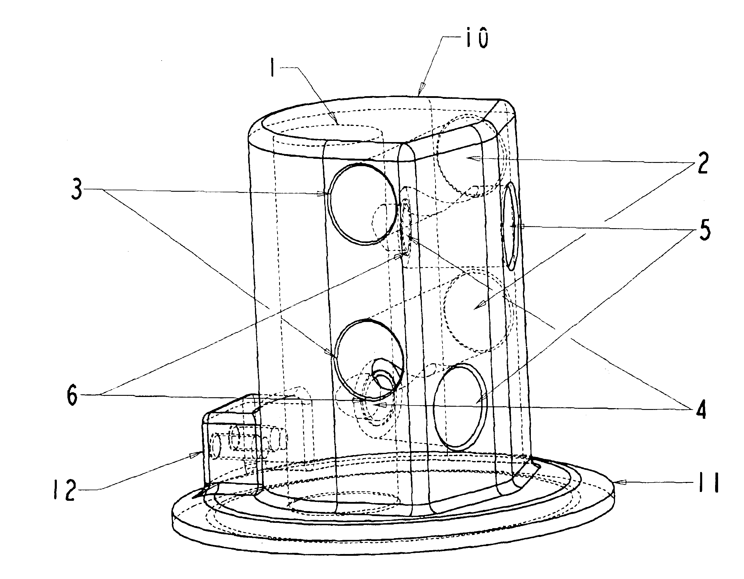
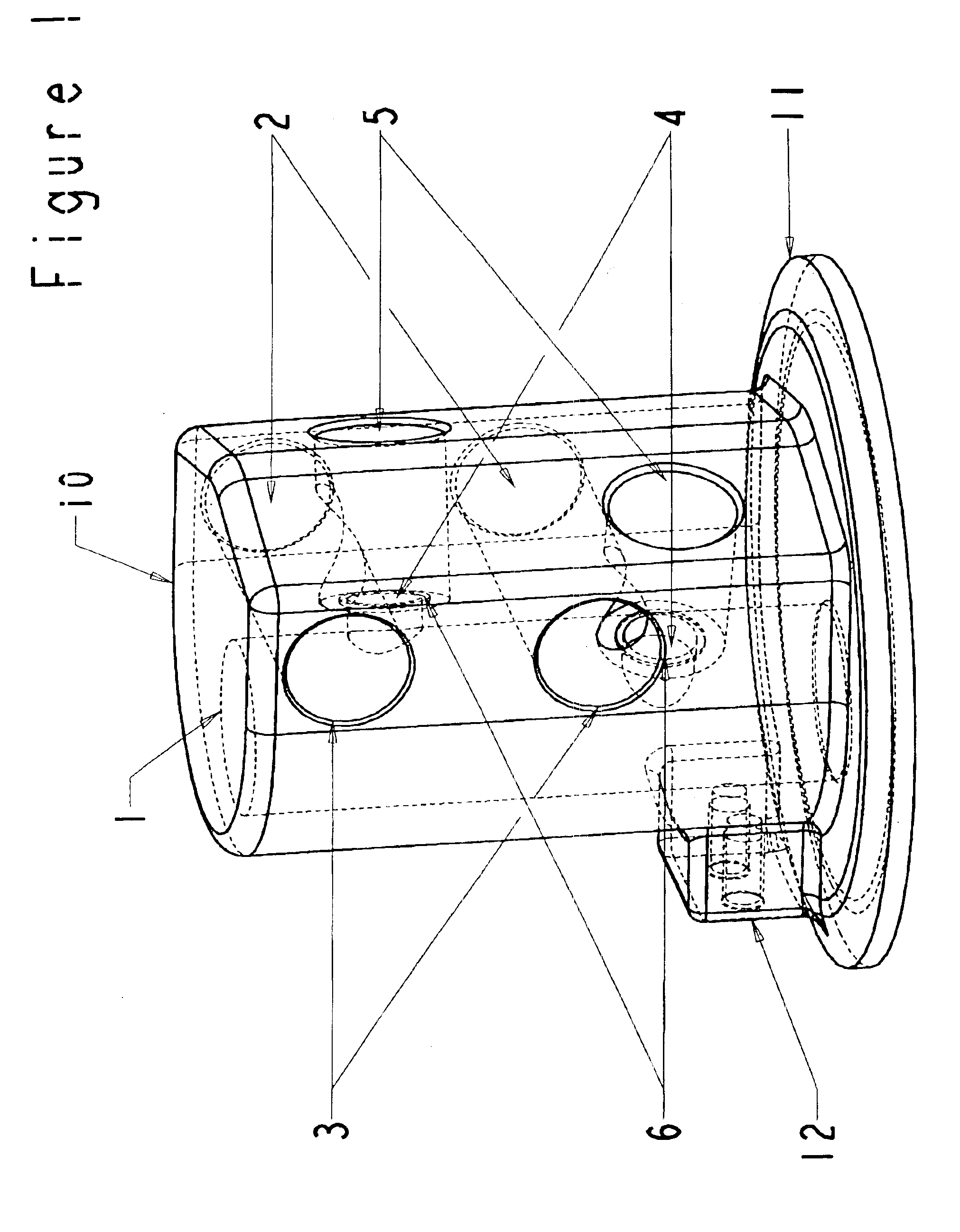
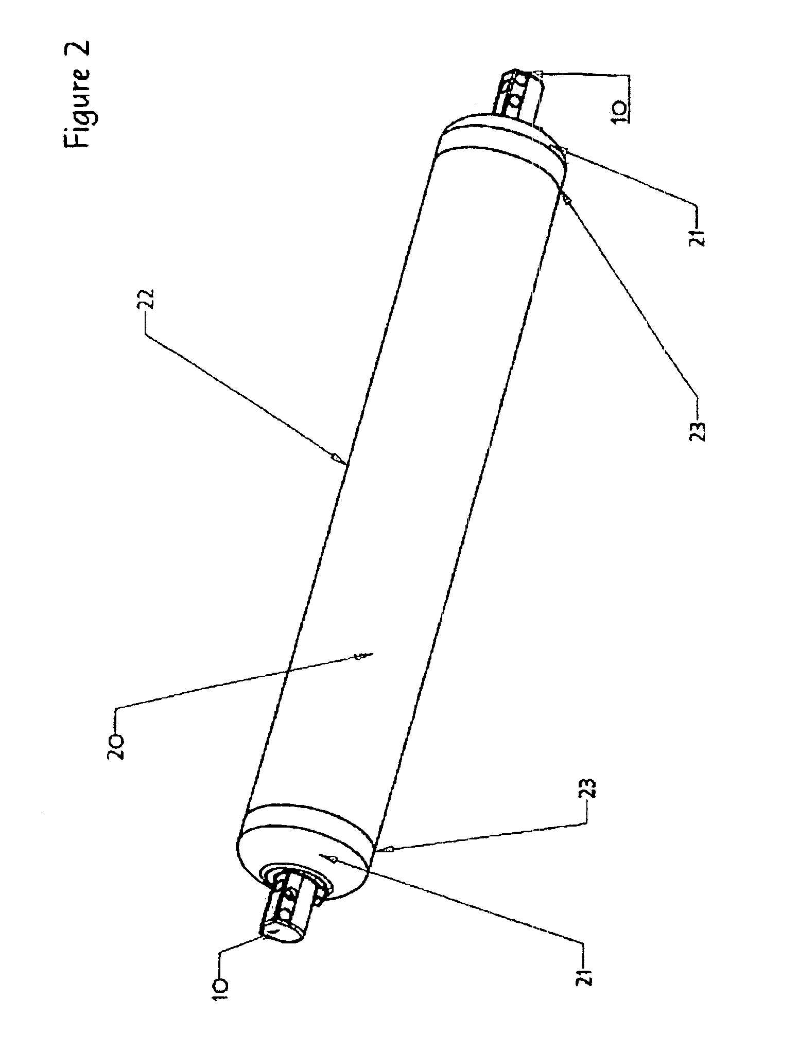
[0027]FIG. 1 depicts a three-dimensional, perspective view of the valve manifold 10 of the present invention. The valve manifold 10 is provided with at least one plenum cavity 1, which is in communication with an adsorbent vessel 20 (see FIG. 2). The manifold 10 is further provided with at least one fluid channel 2, which has at least one fluid inlet port 3. The plenum cavity 1 is in communication with fluid channel 2 via internal gallery or fluid passage 4. Note that the manifold 10 can include one or more channels 2 that are connected to one or more cavities 1 by one or more passages 4. A variety of different configurations will be readily apparent to on...


PUM


Abstract

A pressure swing adsorption system including a pressure vessel having an opening and a valve manifold including a body having a first cavity fluidly connected to the opening. The body further includes a passage and a channel, such that the passage connects the channel to the cavity. The valve manifold further includes a valve provided within the passage. The valve is configured to selectively permit and restrict flow between the channel and the cavity via the passage.

Description

CROSS-REFERENCE TO RELATED APPLICATIONS[0001]This application is a continuation application of U.S. application Ser. No. 10 / 269,067, which was filed on Oct. 11, 2002 now U.S. Pat. No. 6,755,895, and is related to Provisional Application No. 60 / 370,702, entitled IMPROVED METHOD AND APPARATUS FOR PRESSURE SWING ADSORPTION, which was filed on Apr. 9, 2002. The contents of those applications are incorporated herein by reference.BACKGROUND OF THE INVENTION[0002]1. Field of the Invention[0003]The present invention relates to valve assemblies for pressure swing adsorption systems.[0004]2. Discussion of the Background[0005]Pressure Swing Adsorption (PSA) is a technique used to fractionate mixtures of gases to provide at least one purified product gas and a raffinate byproduct mixture. PSA has been successfully used to separate hydrogen from other gases, oxygen and nitrogen from air, helium from natural gas, among others.[0006]Early PSA systems generally used four adsorbent vessels operated ...

Claims


Application Information

Patent Timeline
IPC IPC(8): B01D53/047B01D53/04F16K27/00
CPCB01D53/0446B01D53/047B01D2259/404B01D53/06
Inventor LOMAX, JR., FRANKLIN D.STREEKS, MICHAEL S.
Owner LUMMUS TECH INC
Why Eureka
Try Eureka