Multi-stage amplifier

Active Publication Date: 2005-08-16
FUJITSU LTD
View PDF4 Cites 17 Cited by
  • Summary
  • Abstract
  • Description
  • Claims
  • Application Information

AI Technical Summary

Benefits of technology

[0013]It is an object of the present invention to at l

Problems solved by technology

In general, however, the cascode distributed amplifier has a low gain.
In this amplifier stages, if a pre-amplifier stage is direct current (hereinafter, “DC”) coupled to a post-amplifier stage, since each stage has a different bias level from another, it is difficult to determine the gain definitely.
This capacitor has an

Method used


Image

  • Multi-stage amplifier
  • Multi-stage amplifier
  • Multi-stage amplifier

Examples


Embodiment Construction

[0026]Exemplary embodiments of a multi-stage amplifier relating to the present invention will be explained in detail below with reference to the accompanying drawings.

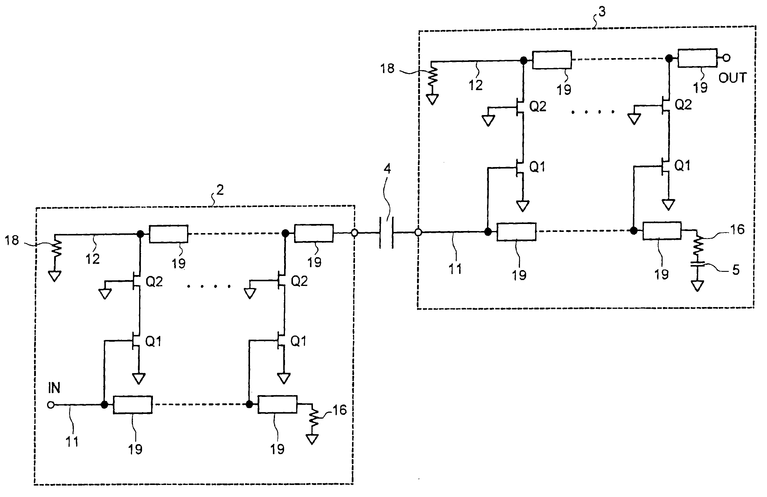
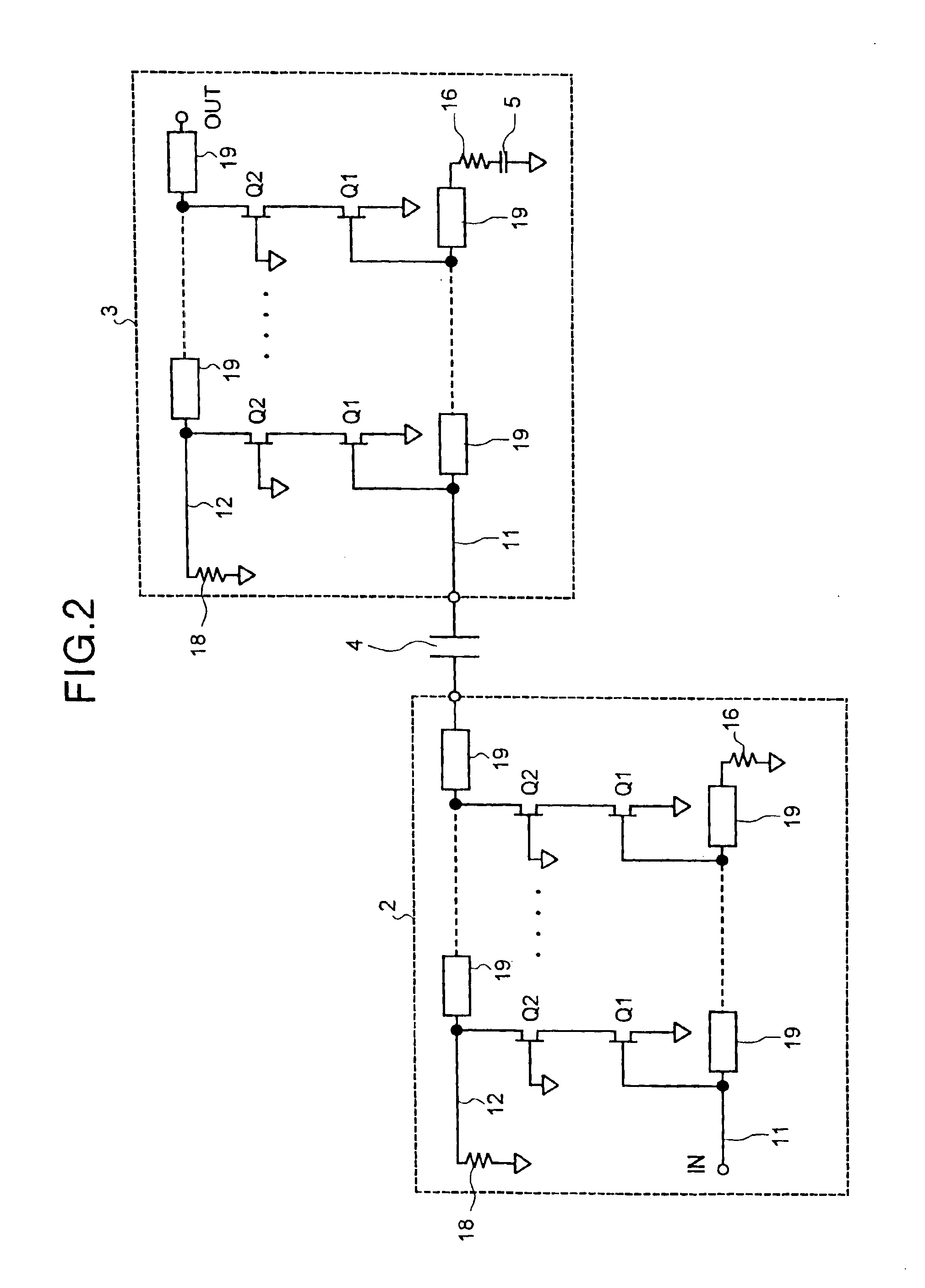
[0027]FIG. 2 is a circuit diagram illustrating the configuration of a multi-stage amplifier according to a first embodiment of the present invention. This multi-stage amplifier is configured to connect a pre-amplifier stage 2 to a post-amplifier stage 3 in cascade via a first capacitor (DC cut capacitor) 4. The output line 12 in the pre-amplifier stage 2 is coupled to the input line 11 in the post-amplifier stage 3 via the first capacitor 4. A second capacitor 5 is connected between the terminal resistor 16 on the input line 11 in the post-amplifier stage 3 and the ground point. In addition, as shown in FIG. 3, a resistor 6 may be connected in parallel with the first capacitor 4.

[0028]The pre-amplifier stage 2 and the post-amplifier stage 3 both include the cascode-type single-phase distributed amplifiers with the same...


PUM


Abstract

A multi-stage amplifier includes first and second amplifier stages, and first and second capacitors. The first amplifier stage includes a input line having a first input end and a second input end; an input terminal block connected to the second input end; an amplifier circuit amplifying a first signal input to the first input end; an output line having a first output end where the first signal amplified is output, and a second output end; and an output terminal block connected to the second output end. The second amplifier stage includes components similar to that of the first amplifier stage. The first capacitor is connected between the first output end of the first amplifier stage and the first input end of the second amplifier stage. The second capacitor is connected to any one of the input and output terminal blocks of the first and second amplifier stages.

Description

CROSS-REFERENCE TO RELATED APPLICATIONS[0001]This application is based upon and claims the benefit of priority from the prior Japanese Patent Application No.2002-309504, filed on Oct. 24, 2002, the entire contents of which are incorporated herein by reference.BACKGROUND OF THE INVENTION[0002]1) Field of the Invention[0003]The present invention relates to a multi-stage amplifier, and more particularly to a high-gain amplifier having a frequency band of more than 40 gigahertz.[0004]2) Description of the Related Art[0005]The rapid spread of the Internet has led to needs for communications systems with high transmission rate (e.g. 40 Gb / s) and high data-capacity. The communications systems require a high-gain amplifier having a frequency band of more than 40 gigahertz in a driver circuit for driving a modulator at a transmitter front end as well as in a preamplifier or an equalizer amplifier at a receiver front end.[0006]Distributed amplifiers have a frequency band determinable from a l...

Claims


Application Information

Patent Timeline
IPC IPC(8): H03F1/08H03F3/189H03F3/193H03F1/22H03F3/60H03F3/68
CPCH03F1/223H03F1/226H03F3/193H03F3/1935H03F2200/54
Inventor SHIGEMATSU, HISAO
Owner FUJITSU LTD
Why Eureka
Try Eureka