Liquid crystal panel driving method, liquid crystal device, and electronic apparatus

a technology of liquid crystal devices and driving methods, applied in the direction of instruments, computing, electric digital data processing, etc., can solve problems such as image degradation, and achieve the effects of preventing image degradation, high-quality image, and preventing flicker

Inactive Publication Date: 2005-08-16
BOE TECH GRP CO LTD
View PDF11 Cites 36 Cited by
  • Summary
  • Abstract
  • Description
  • Claims
  • Application Information

AI Technical Summary

Benefits of technology

[0018]Accordingly, the Inventors propose to change the frequency of the driving signal depending on the temperature, thereby maintaining the threshold voltage Vth of the liquid crystal panel 10 substantially constant. For example, concerning the driving signals shown in FIGS. 5(A) and (B), when one frame period is 16.6 msec and 32 X electrodes are driven, the frame frequency is 60 Hz and one selection period is 518.8 μsec. Under these conditions, when an image signal repetitively becomes on and off, the frequency of the signal applied to the liquid crystal layer 15 becomes a maximum of 1.92 kHz. In contrast, when the temperature decreases, the frequency of the driving signal is reduced to, for example, 1 / 2. Hence, the frequency becomes 0.96 kHz. Even when the temperature is −20° C., the dielectric anisotropy Δε is substantially flat. At this time, the frame frequency is 30 Hz. When the frequency of the driving signal is changed depending on the temperature, it is possible to prevent the dielectric anisotropy Δε from varying with frequency. Hence, it is possible to suppress large variations in the threshold voltage Vth.
[0021]Therefore, according to the present invention, when the ambient temperature decreases, the liquid crystal panel is driven by the driving frequency at a frequency in which the dielectric anisotropy Δε does not vary. Hence, the contrast is not degraded.
[0022]According to various exemplary embodiments of the present invention, it is preferable that a high frequency signal higher than that used at the normal temperature be used as the driving signal at a high temperature based on the temperature detection results. When the ambient temperature increases, it is not necessary to take variations in the dielectric anisotropy Δε into consideration. Instead, it is necessary to drive the liquid crystal panel with a cycle in accordance with the motion of the liquid crystal molecules. According to various exemplary embodiments of the present invention, when the temperature increases, the frequency of the driving signal is set to be high. The subsequent writing is performed before the liquid crystal molecules respond. This prevents degradation of the image quality. Even when the temperature increases, it is possible to display a high-quality image.
[0023]According to various exemplary embodiments of the present invention, it is preferable that the frequency of the driving signal vary discontinuously with respect to the temperature. For example, a frame frequency obtained when performing time-division driving of a plurality of pixels arranged in a matrix form on the liquid crystal panel is varied, based on the temperature detection results, so that at least a frequency corresponding to an integer multiple of 50 Hz is avoided. In addition, the frame frequency obtained when performing time-division driving of a plurality of pixels arranged in a matrix form on the liquid crystal panel is varied, based on the temperature detection results, so that at least a frequency corresponding to an integer multiple of 60 Hz is avoided. With this arrangement, the frame frequency does not overlap the frequency of the commercial power supply. It is thus possible to prevent flicker from occurring in an image displayed under fluorescent light.
[0028]According to various exemplary embodiments of the present invention, it is preferable that the temperature compensating device discontinuously varies the frequency of the driving signal with respect to the temperature. For example, the temperature compensating device varies a frame frequency obtained when performing time-division driving of a plurality of pixels arranged in a matrix form on the liquid crystal panel, based on the temperature detection results, so that at least a frequency corresponding to an integer multiple of 50 Hz is avoided. In addition, the temperature compensating device varies a frame frequency obtained when performing time-division driving of a plurality of pixels arranged in a matrix form on the liquid crystal panel, based on the temperature detection results, so that at least a frequency corresponding to an integer multiple of 60 Hz is avoided.

Problems solved by technology

This problem may result from the fact that frequency characteristics of the dielectric anisotropy Δε of the liquid crystal strongly vary with temperature.
Hence, there is a problem in that the image may be degraded.

Method used


Image

  • Liquid crystal panel driving method, liquid crystal device, and electronic apparatus
  • Liquid crystal panel driving method, liquid crystal device, and electronic apparatus
  • Liquid crystal panel driving method, liquid crystal device, and electronic apparatus

Examples


exemplary embodiment 1

[0055](Overall structure)

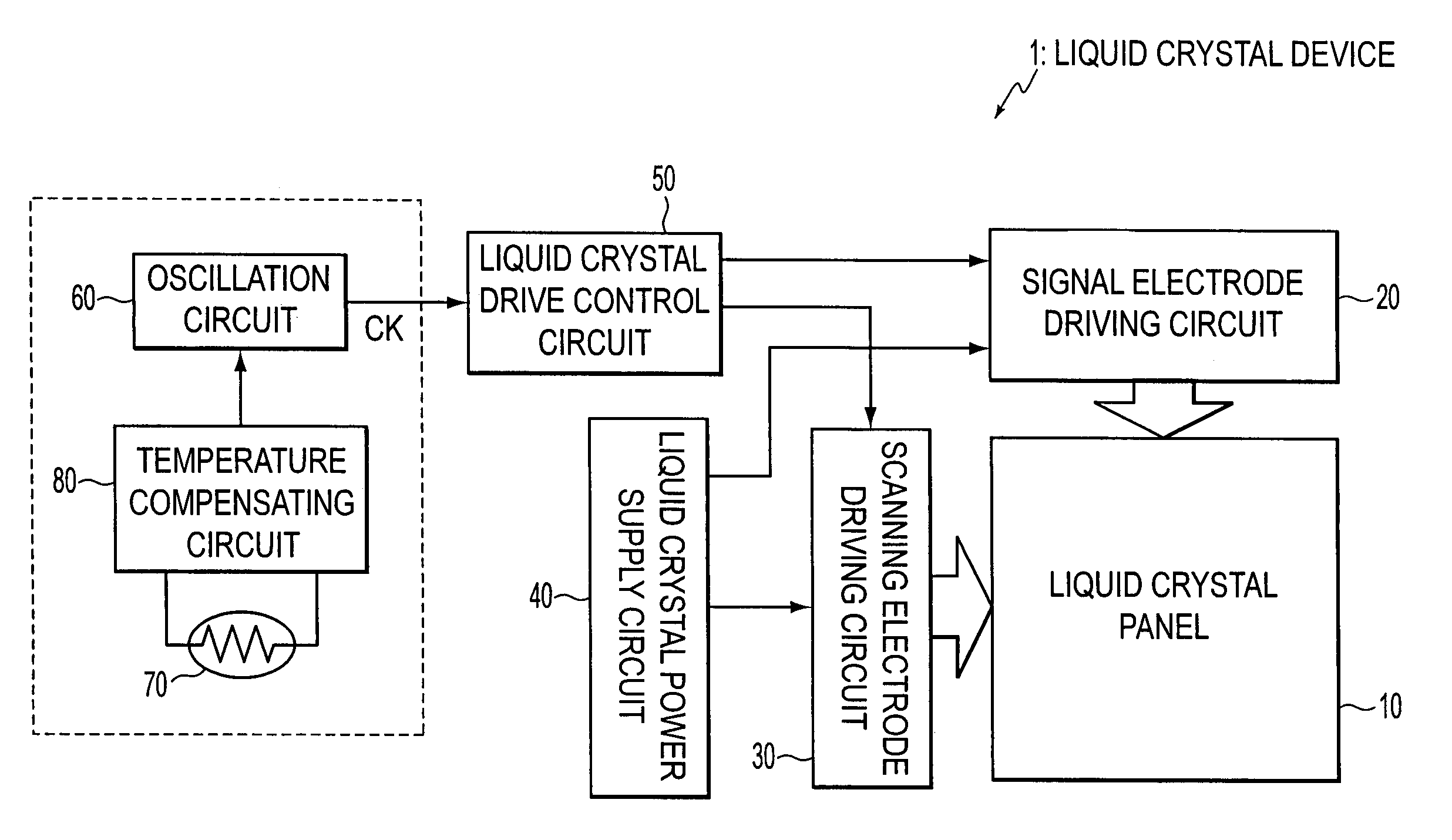
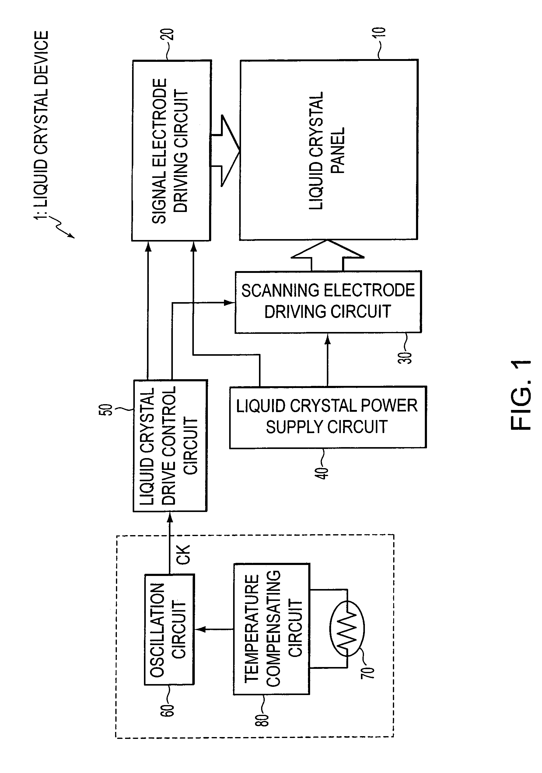
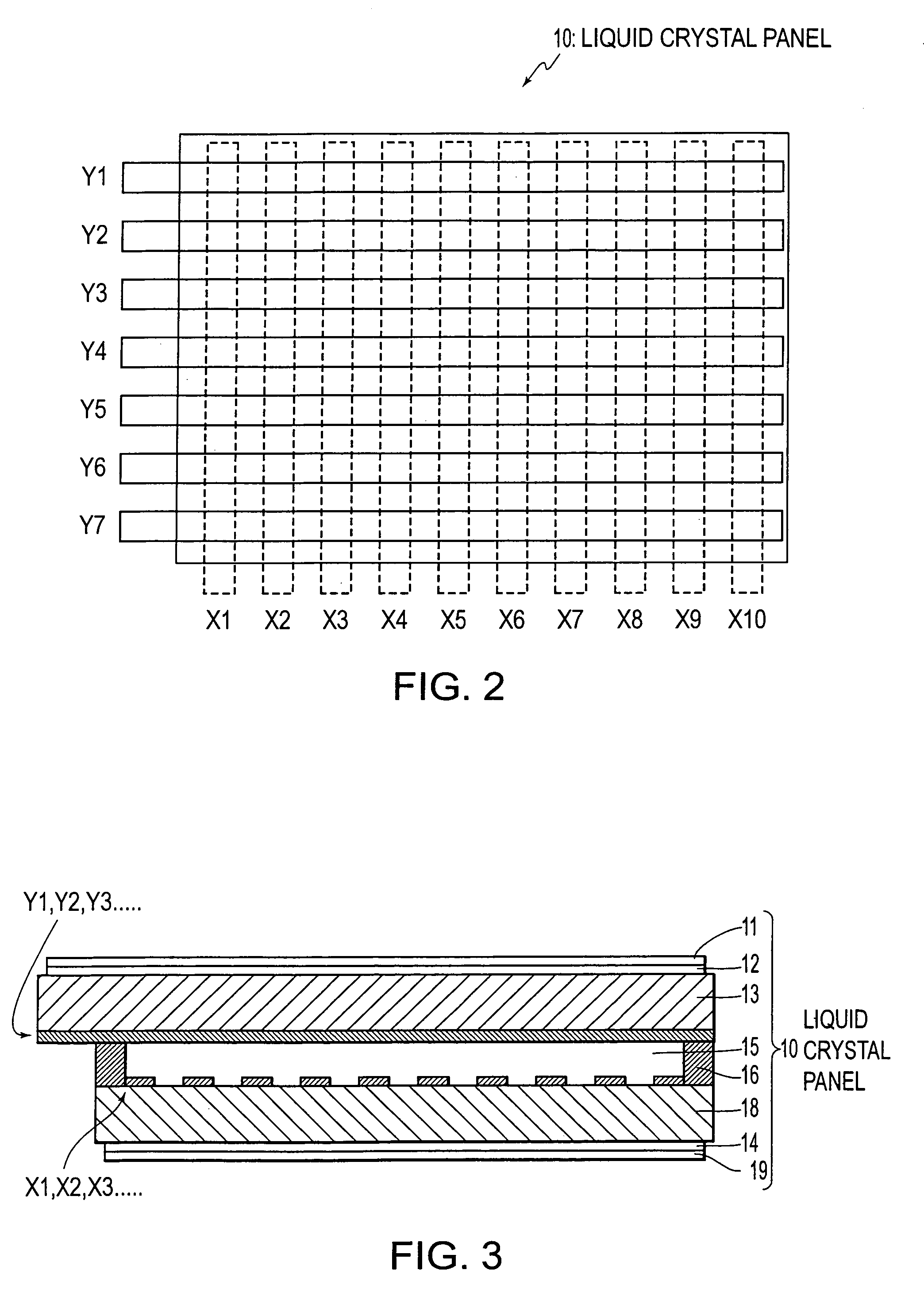
[0056]FIG. 1 is a block diagram of the schematic structure of a liquid crystal device according to a first exemplary embodiment of the present invention. FIGS. 2 and 3 are a plan view and a sectional view, respectively, of a liquid crystal panel 10 used in the liquid crystal device. FIG. 4 is an equivalent circuit diagram of the liquid crystal panel 10. FIG. 5 includes waveform charts of driving signals used for the liquid crystal device.

[0057]As shown in FIG. 1, a simple matrix liquid crystal device 1 of this exemplary embodiment includes the liquid crystal panel 10, driving circuits (a signal electrode driving circuit 20 and a scanning electrode driving circuit 30) for driving the liquid crystal panel 10, a liquid crystal power supply circuit 40 for supplying various DC power (potentials V1, V2, V3, . . . shown in FIG. 5) to the driving circuits 20 and 30, and a liquid crystal drive control circuit 50 for controlling the driving circuits 20 and 30 and caus...

exemplary embodiment 2

[0083]FIG. 11 is a block diagram of the structure of a temperature-compensated oscillator for outputting a reference clock signal to a liquid crystal drive control circuit 50 included in the structure of a liquid crystal device of another exemplary embodiment. According to this exemplary embodiment and the following exemplary embodiments, the basic structures of a liquid crystal device 1 and a liquid crystal panel 10 are the same as those described in the first exemplary embodiment with reference to FIGS. 1 to 5. The same reference numerals are given to corresponding components, and repeated descriptions of the common portions are omitted. The characteristics of the liquid crystals used for the liquid crystal device are the same as those described with reference to FIGS. 8 to 10B, and descriptions thereof are omitted.

[0084]According to the embodiment, as shown in FIG. 11, a low frequency signal is used as a driving signal at a low temperature and a high frequency signal is used at a...

exemplary embodiment 3

[0097]FIG. 13 is a block diagram of the structure of a temperature-compensated oscillator for outputting a reference clock signal to a liquid crystal drive control circuit 50 included in the structure of a liquid crystal device of another exemplary embodiment.

[0098]According to this exemplary embodiment, as shown in FIG. 13, based on the detection results obtained by a temperature sensor 70, a low frequency signal is used as a driving signal at a low temperature and a high frequency signal is used at a high temperature. To this end, a temperature compensating circuit 80 using an arithmetic circuit 83 is formed. According to the embodiment, a voltage-controlled oscillator is used as an oscillator 60.

[0099]Since the temperature compensating circuit 80 is provided with the arithmetic circuit 83 for performing predetermined arithmetic processing, a reference clock signal CK is output from the voltage-controlled oscillator (oscillator 60) to the liquid crystal drive control circuit 50 so...


PUM


Abstract

A liquid crystal panel driving method is provided for optimizing driving conditions by performing temperature compensation without varying the voltage of a driving signal. In the liquid crystal device, based on a temperature detection result by the temperature sensor, a temperature compensating circuit sets the frame frequency of driving signals output from driving circuits to a liquid crystal panel at a low temperature, thereby performing temperature compensation so that the liquid crystal device is operated under a condition in which the dielectric anisotropy of the liquid crystal is substantially flat. In accordance with the fact that the motion of the liquid crystal molecules becomes active at a high temperature, the temperature compensating circuit sets the frame frequency of the driving signals to be high. Concerning the frame frequency, 50 Hz (or 60 Hz) and an integer multiple of that frequency are avoided.

Description

BACKGROUND OF THE INVENTION[0001]1. Field of Invention[0002]The present invention relates to liquid crystal panel driving methods, liquid crystal devices, and electronic apparatuses. More particularly, the present invention relates to a temperature compensating technique employed when driving a liquid crystal panel.[0003]2. Description of Related Art[0004]Concerning liquid crystal devices used for various matrix liquid crystal displays, for example, a simple matrix liquid crystal device includes, as shown in FIG. 18, a liquid crystal panel 10, driving circuits (a signal electrode driving circuit 20 and a scanning electrode driving circuit 30) for driving the liquid crystal panel 10, a liquid crystal power supply circuit 40 for supplying various DC power to the driving circuits 20 and 30, and a liquid crystal drive control circuit 50 for controlling the driving circuits 20 and 30 and causing the driving circuits 20 and 30 to output predetermined driving signals to the liquid crystal ...

Claims


Application Information

Patent Timeline
IPC IPC(8): G02F1/13G02F1/133G09G3/36
CPCG09G3/3622G09G3/3611G09G2310/08G09G2320/0247G09G2320/041G09G2340/0435
Inventor IIJIMA, CHIYOAKIIKEDA, MINORU
Owner BOE TECH GRP CO LTD
Why Eureka
Try Eureka