Jitter histogram approximation

Inactive Publication Date: 2005-08-16
AGILENT TECH INC
View PDF18 Cites 22 Cited by
  • Summary
  • Abstract
  • Description
  • Claims
  • Application Information

AI Technical Summary

Benefits of technology

[0006]It is an object of the invention to provide an improved jitter measurement. The object

Problems solved by technology

Random jitter is unbounded and caused by data-independent effects, such as thermal noise etc.

Method used


Image

  • Jitter histogram approximation
  • Jitter histogram approximation
  • Jitter histogram approximation

Examples


Embodiment Construction

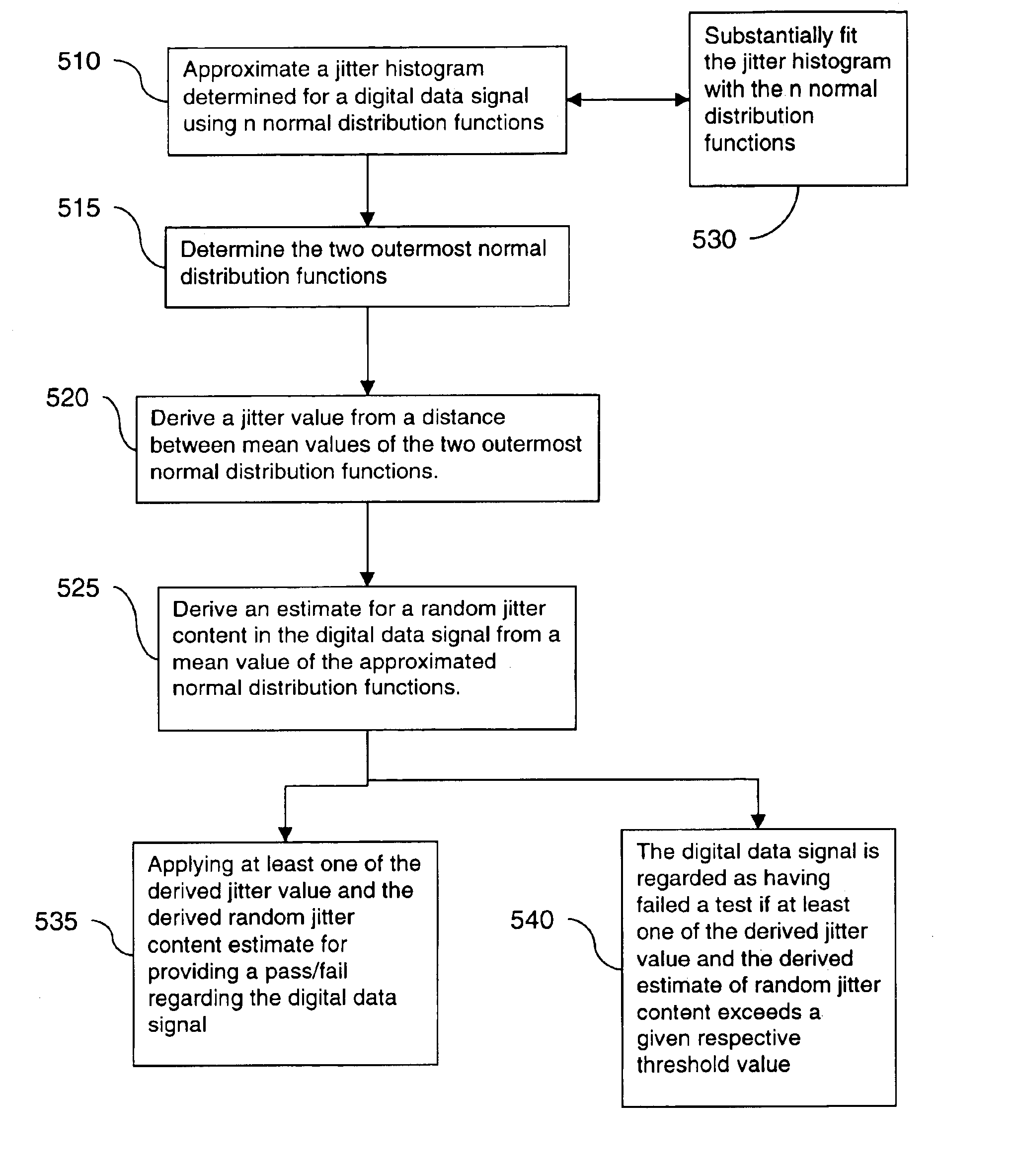
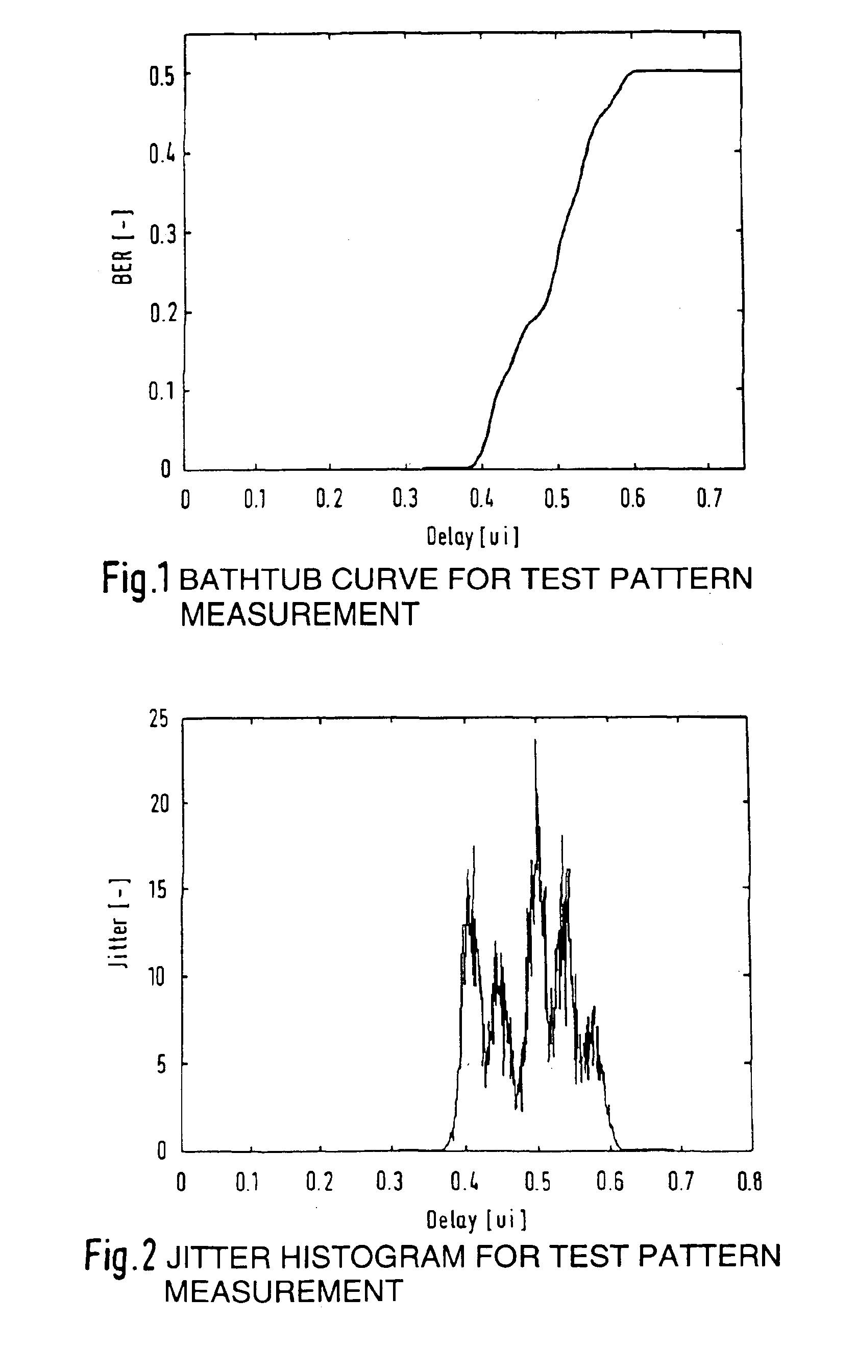
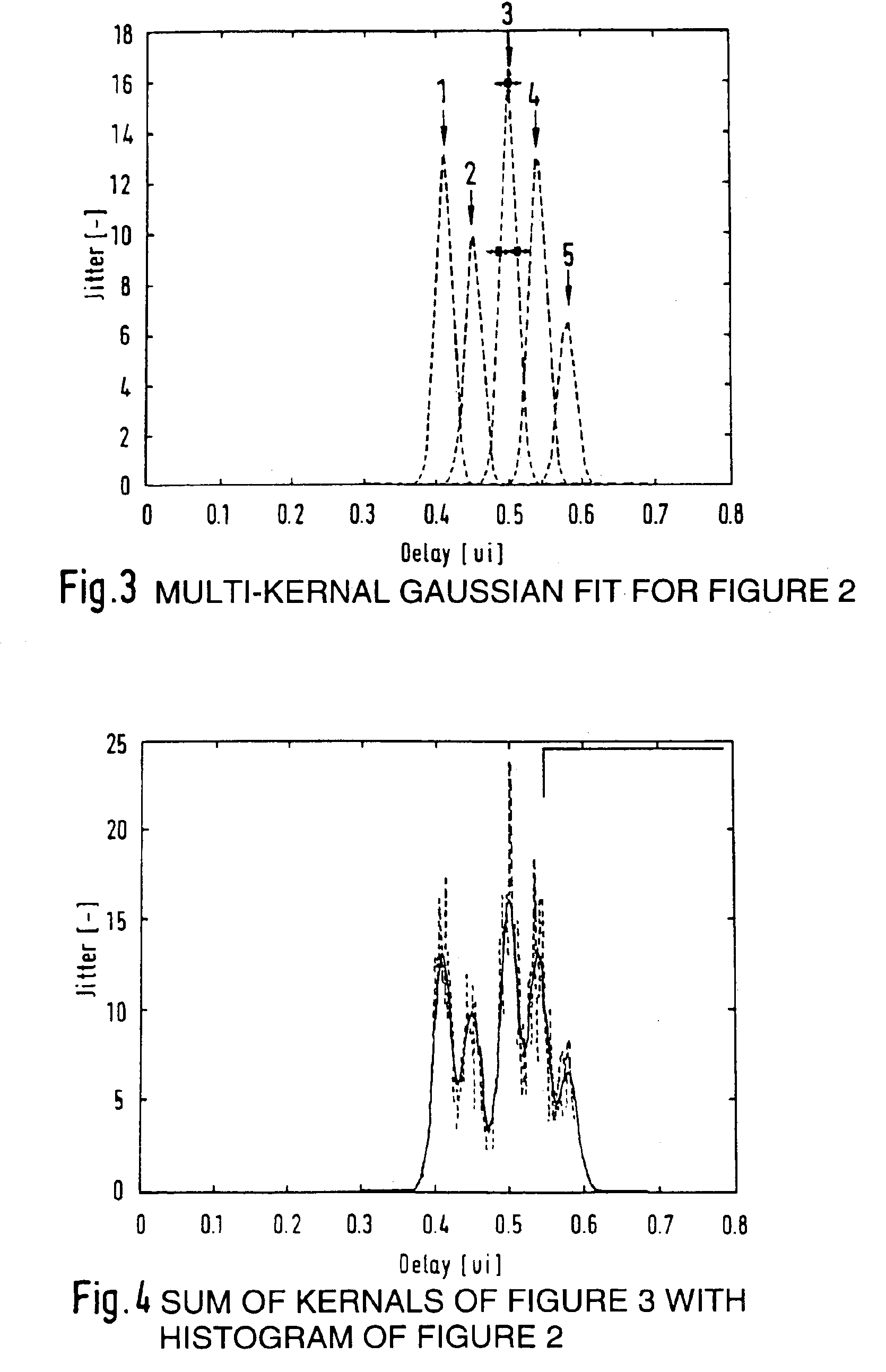
[0028]In a preferred embodiment for obtaining a jitter value (substantially representing the data-dependent or deterministic jitter amount) of a digital data signal to be measured, the following steps are executed using e.g. the aforementioned Agilent® 81250 ParBERT®:[0029]1) A bathtub curve is determined for the digital data signal (e.g. a real-life signal or a test pattern such as a PRBS). Since both halves of the bathtub curve contain substantially the same jitter information, only the right side is considered (FIG. 1, with the x-axis denoting the delay time in unit intervals ui, and the y-axis denoting BER values). FIG. 2 shows the jitter histogram (in linear scale) derived from FIG. 1.[0030]2) FIG. 3 shows an example of a multi-kernel Gaussian distribution fit for the histogram data of FIG. 2:

[0031]

Kernel#MeanStd. Dev.Relative Weight10.41 ui0.0123 ui0.420.45 ui0.0121 ui0.33 0.5 ui0.0124 ui0.540.54 ui0.0123 ui0.450.58 ui0.0122 ui0.2

[0032]FIG. 4 shows the sum of the determined ke...


PUM


Abstract

For determining a jitter value for a digital data signal, a jitter histogram determined for the digital data signal is substantially approximated using n normal distribution functions. The two outermost normal distribution functions are determine, and the jitter value is derived from a distance between the mean values of the two outmost distribution functions.

Description

BACKGROUND OF THE INVENTION[0001]The present invention relates to jitter measurements for digital data communication testing.[0002]Characterizing the transient behavior of high-speed digital circuits, i.e. the transition from a logical zero to a logical one and vice versa, has become increasingly important for designing as well as manufacturing such digital circuits. Timing problems can cause single transmission errors, or temporary or even permanent outage of an entire communication system, and have to be avoided. The standard overall figure of merit for a communications system is the Bit Error Rate (BER), however a high value of BER does not necessarily indicate timing problems, as there are many other potential sources of error in a system (for example level / threshold mismatch).[0003]One of the key specifications of high-speed circuits with respect to timing is Jitter. ITU-T G.701 defines jitter as short-term non-cumulative variations of the significant instants of a digital sign...

Claims


Application Information

Patent Timeline
IPC IPC(8): H04L1/24H04L1/20G01R29/02H04L25/02
CPCH04L1/205H04L1/24
Inventor MUELLER, MARCUS
Owner AGILENT TECH INC
Why Eureka
Try Eureka