Multi-spool turbogenerator system and control method

a turbogenerator and multi-spool technology, applied in the direction of engine starters, engine/propulsion engine ignition, lighting and heating apparatus, etc., can solve the problems of relatively low efficiency of small engines used in such systems, the relatively high cost of power from distributed generation systems, and the failure of distributed generation to achieve widespread deployment. achieve the effect of reducing the need for variable-geometry mechanisms, reducing the need for pre-burners, and substantially optimizing engine efficiency

Inactive Publication Date: 2005-08-23
MES INT INC
View PDF16 Cites 84 Cited by
  • Summary
  • Abstract
  • Description
  • Claims
  • Application Information

AI Technical Summary

Benefits of technology

[0014]The present invention addresses the above needs and achieves other advantages, by providing an electrical power generating system and method employing a multi-spool engine, wherein at any operating condition, for a given power output the engine efficiency can be substantially optimized by controlling the rate of air flow through the engine in such a manner that the fuel / air ratio is controlled to maintain a high peak temperature imparted to the working fluid in the engine. The method and system of the invention can eliminate the need for variable-geometry mechanisms in the engine, eliminate the need for variable-geometry combustors, and also minimize or eliminate the need for pre-burners.
[0015]In accordance with a method aspect of the invention, a method is provided for controlling operation of a twin-spool turbine engine in an electrical generator system. The system has a first shaft on which a first turbine and a first compressor are mounted to form a first spool or gasifier spool. The first spool includes a combustor for combusting or reacting an air / fuel mixture to produce hot gases that drive the first turbine. The system also includes a second shaft on which at least a second turbine is mounted to form a second spool that is rotatable independently of the first spool (i.e., there is no mechanical linkage between the spools). Exhaust gases from the first turbine are fed to the second turbine, which drives the second spool. A main electrical generator is coupled to one of the shafts such that rotation of the shaft causes the main generator to operate to create an alternating electrical current; a change in speed of the main generator causes a corresponding change in speed of the shaft and hence a change in rate of air flow through the compressor on that shaft. An auxiliary generator / motor is coupled to the other of the shafts. In a generation mode, the auxiliary generator / motor is driven by its shaft to extract power from the shaft and produce electrical power; in a motor mode, the auxiliary generator / motor is supplied with electrical power and injects mechanical power into its shaft. The power extraction / injection capability of the auxiliary generator / motor is used to achieve various desirable effects in the engine system, including speed control for the shaft on which the generator / motor is mounted. Through such speed control for the spool on which the generator / motor is mounted, the air flow rate through the associated compressor and / or the pressure ratio of the compressor can be controlled at any operating condition, thereby providing control over the operating line for the compressor. The operating line is the line on the pressure ratio-versus-flow graph for the compressor (referred to as the compressor “map”) along which the compressor operates with changing turbine power output. The location of the operating line on the map in general is a function of the ambient temperature. The control over the operating line provided by the invention can be used to achieve one or more effects, which include optimizing the efficiency of the engine at any operating condition, and / or avoiding a surge region of a compressor map, and / or preventing over-heating of a recuperator included in the engine system, and / or maintaining a catalytic combustor inlet temperature above a catalyst minimum operating temperature. In addition, the generator / motor can rotatably drive the shaft on which it is mounted during start-up so as to serve as a starter so that a separate starter can be omitted.

Problems solved by technology

Distributed power generation is a concept that has been the subject of much discussion over the years, but to date there has not been widespread deployment of distributed generation systems.
The failure of distributed generation to achieve widespread deployment can be attributed primarily to cost.
A major factor driving the relatively high cost of power from distributed generation systems has been the relatively low efficiency of the small engines used in such systems, particularly at part-load operation conditions.
Because of the relatively small amount of electrical power required from a distributed generation system, the turbine engine is correspondingly small.
Accordingly, microturbines and miniturbines automatically have an efficiency disadvantage relative to larger engines.
Furthermore, irrespective of size, the part-load efficiency of a turbine engine is notoriously poor, in part because of the particular manner in which the engine is operated at part-load conditions.
Therefore, if the engine, when operating at a part-load condition, is controlled in such a manner that the peak effective temperature of the working fluid in the cycle (i.e., the turbine inlet temperature) is substantially lower than what it is at the design point, the efficiency of the engine tends to suffer to a substantial extent.
Such variable-geometry systems are expensive, and the bearings and other movable components are prone to wear, thus making these systems impractical for electrical generation systems that must be available for service for a high percentage of hours per year, must be able to operate essentially continuously if required, and must also be able to respond quickly to changes in the power required by the load being served.
Furthermore, variable-geometry mechanisms are not practical to implement in microturbines and miniturbines because of the small size of the engine.
Emissions (including but not limited to nitrogen oxides, unburned hydrocarbons, and carbon monoxide) represent another aspect of distributed generation that has proven challenging.
These trends continue and the flame zone becomes more unstable as the mixture is made still leaner, until the lean extinction limit is reached.
In practice, carbon monoxide and unburned hydrocarbon emissions and / or pressure pulsations become unacceptably high before the lean extinction limit is reached.
Catalytic combustion does, however, introduce another constraint on operation called the lower catalytic activity limit.
In the case of conventional lean pre-mixed combustion, this tends to result in increased emissions; in the case of catalytic combustion, the falling combustor inlet temperature can lead to failure to sustain catalytic combustion.
The pre-burner solution poses a reliability penalty in that over-temperature or other malfunction of the pre-burner can damage the main burner, and also adds to the cost of the system.
In addition, it imposes an operating cost penalty as a result of the pressure loss that occurs through the pre-burner; this pressure loss is experienced even when the pre-burner is not in use.
However, variable geometry solutions are costly, complicated, and prone to excessive wear, decreasing reliability and increasing maintenance costs.
As noted, twin-spool engines have an advantage in terms of higher power output, but they also further complicate the control of the engine, particularly when (as desirable) there is no mechanical link between the two shafts so that all control must be achieved by regulation of the flow.
Such engines generally require a complicated mechanical clutch and gear train between the shafts.
Such mechanisms are costly to manufacture, prone to wear, and have high losses.
They are generally unsuitable for power generation applications where operating lives of 60,000 hours or more without maintenance are desirable.
For many potential users, these factors have combined to make electrical power generation via distributed generation systems less attractive than purchasing power from the large utilities.

Method used


Image

  • Multi-spool turbogenerator system and control method
  • Multi-spool turbogenerator system and control method
  • Multi-spool turbogenerator system and control method

Examples


Embodiment Construction

[0036]The present inventions now will be described more fully hereinafter with reference to the accompanying drawings, in which some, but not all embodiments of the invention are shown. Indeed, these inventions may be embodied in many different forms and should not be construed as limited to the embodiments set forth herein; rather, these embodiments are provided so that this disclosure will satisfy applicable legal requirements. Like numbers refer to like elements throughout.

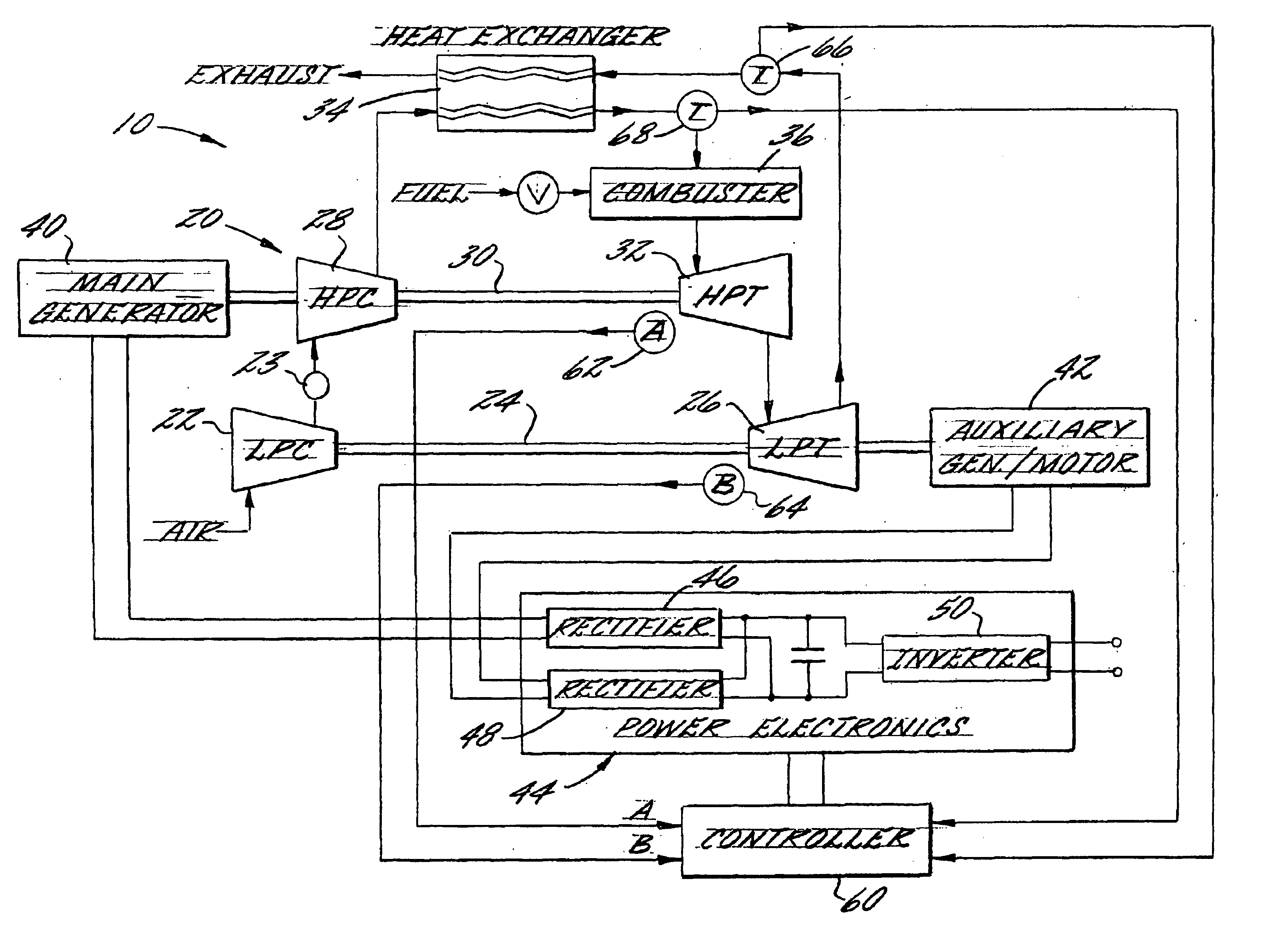
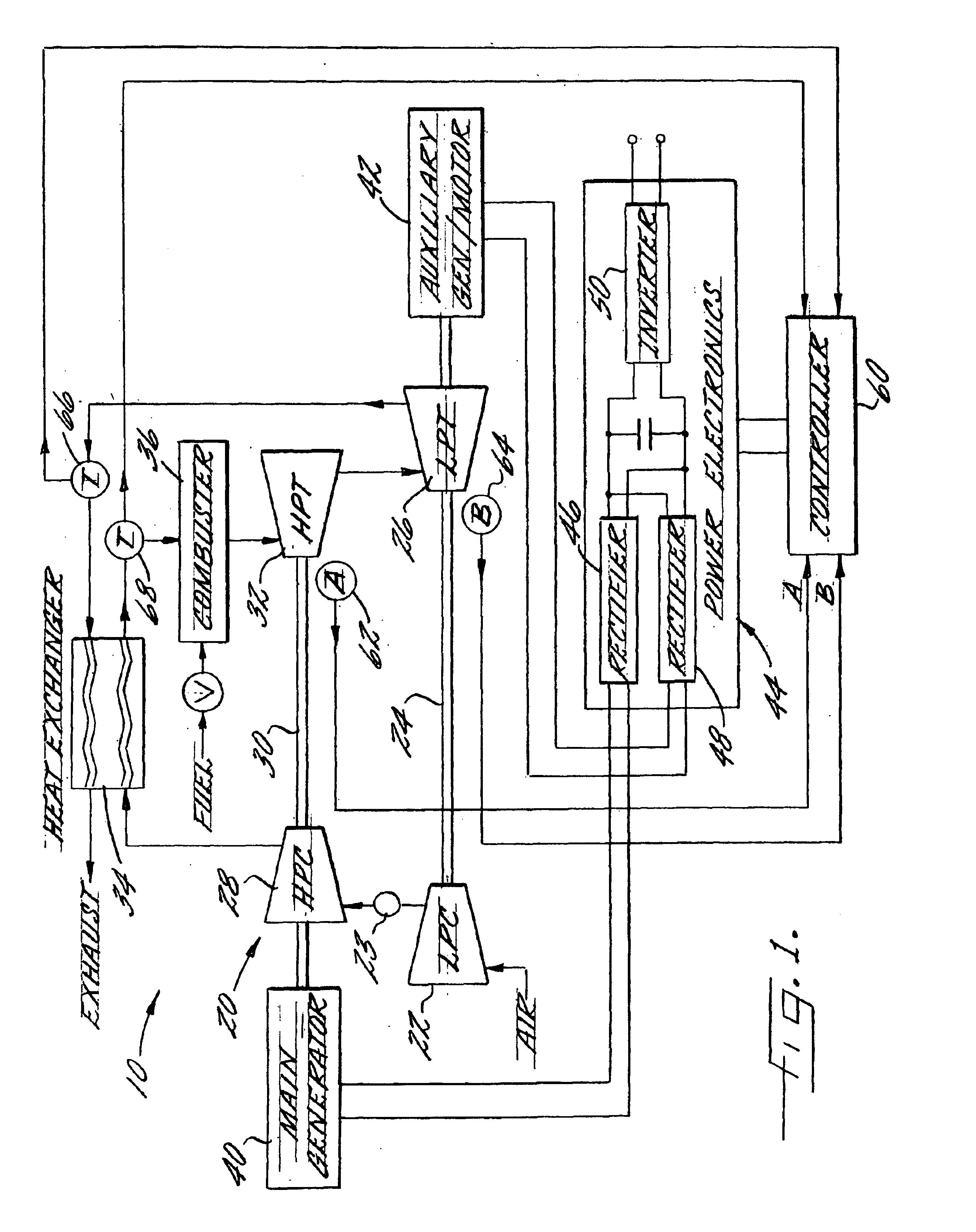
[0037]An electrical generator system 10 in accordance with one embodiment of the invention is schematically shown in FIG. 1. The system includes a gas turbine engine 20 that burns a mixture of fuel and air to produce hot combustion gases that are then expanded to create mechanical power. In the illustrated embodiment, the turbine engine includes a low-pressure spool and a high-pressure spool. The low-pressure spool comprises a low-pressure compressor 22 mounted on one end of a rotatable shaft 24 and a low-press...


PUM


Abstract

An electrical power generating system is driven by a multi-spool gas turbine engine including at least first and second spools. The first spool comprises a turbine and a compressor mounted on a first shaft; the second spool has at least a turbine mounted on a second shaft that is not mechanically coupled to the first shaft. A main generator is coupled with one of the spools, and an auxiliary generator / motor is also coupled with one of the spools. Speed control of each of the generators is employed for controlling operation of the engine. The auxiliary generator / motor can operate in either a generation mode to extract power from its spool or a motor mode to inject power into its spool.

Description

FIELD OF THE INVENTION[0001]This invention relates to the generation of electrical power from mechanical power produced by a multi-spool turbine engine.BACKGROUND OF THE INVENTION[0002]Distributed power generation is a concept that has been the subject of much discussion over the years, but to date there has not been widespread deployment of distributed generation systems. Distributed generation refers to the use of small electrical power generation systems located at the sites where the power is needed, and thus is to be distinguished from the traditional utility grid system in which a large central power plant produces power that is then transmitted over substantial distances to a plurality of users through a system of power transmission lines commonly referred to as a grid. In contrast to conventional power plants operated by utilities, which often can produce several megawatts of power, distributed generation systems are generally sized below two megawatts, and more typically in...

Claims


Application Information

Patent Timeline
Patent Type & Authority Patents(United States)
IPC IPC(8): F02C3/00F02C3/113F02C9/28F02C7/26F02C9/00F02C9/32F02C7/275F02B1/12F02B1/00
CPCF02C3/113F02C7/275F02C9/28F02C9/32F02B1/12F25B7/00F01D15/10
Inventor BELOKON, ALEXANDER A.SENKEVICH, MIKHAIL V.TOUCHTON, GEORGE L.
Owner MES INT INC
Why Eureka
Try Eureka