Capacitor discharge ignition

a technology of capacitors and ignition systems, applied in the field of capacitor discharge ignition systems, can solve the problems of inability to meet the needs of small engine applications, so as to avoid use, prevent the engine from reversing, and improve the starting effect of the engin

Inactive Publication Date: 2005-08-23
WALBRO ENGINE MANAGEMENT
View PDF13 Cites 19 Cited by
  • Summary
  • Abstract
  • Description
  • Claims
  • Application Information

AI Technical Summary

Benefits of technology

[0009]In accordance with a second aspect of the present invention, the trigger circuit further includes a trigger coil that generates the trigger signal, which is phased from the timing signal generated by the timing coil. Furthermore, a capacitor is connected across the timing coil so as to provide skip-spark speed-governing at relatively high engine speeds. In other words, the capacitor selectively prevents a spark ignition event at engine operating speeds above a predetermined threshold speed.
[0011]In accordance with a fourth aspect of the present invention, the timing circuit includes a capacitor operatively connected to the charge coil and to the control electrode of the second switch for disabling the trigger segment to prevent reverse rotation of the engine. A third switch has primary current conducting electrodes connected across the capacitor and further has a control electrode coupled to the timing coil, whereby the third switch discharges the capacitor to permit forward rotational operation. Accordingly, the CDI system prevents startup kick-back and reverse rotation operation of the engine.
[0012]Objects, features, and advantages of this invention include providing a capacitor discharge ignition system which improves starting of an engine, provides ignition spark at relatively low engine cranking speed, avoids use of relatively expensive microprocessor circuits, prevents over-speed operation of the engine, reduces delivery of unburned fuel to exhaust, retards engine timing at relatively high speeds, prevents ignition spark when the engine rotates in reverse to prohibit powered running in a reverse direction of rotation, is particularly well adapted for use in small two-stroke and four-stroke engine applications such as for chainsaws, is of relatively simple design and economical manufacture and assembly, and in service has a long, useful life.

Problems solved by technology

Microprocessor electronic timing control systems have been proposed for large engine applications, such as automotive engines, but typically are not well-suited to small engine applications because of cost and packaging constraints.
However, cost constraints associated with microprocessor ignition systems are prohibitive in most small engine applications.
Furthermore, engine overspeed is a problem in many small engine applications, such as chainsaws.
It is possible for an engine to accelerate to an RPM range at which engine components and a saw blade can become damaged, such as where a load on a chainsaw is suddenly removed when the engine is operating at full throttle.
Mechanical and microprocessor speed governors are typically employed to alleviate this problem, but are space-consuming and / or expensive, and often lead to unburned fuel in the engine exhaust.
Reverse startup and sustained operation may result in damage to the chainsaw and may result in a startup “kick-back” condition.
Thus, prior ignition systems are not yet fully optimized to provide a comprehensive ignition system that includes the ability to start the engine at a relatively low engine cranking speed, does not require relatively expensive microprocessor circuits, does not succumb to engine over-speed conditions, does not suffer from startup kick-back, and is of relatively simple design.

Method used


Image

  • Capacitor discharge ignition
  • Capacitor discharge ignition
  • Capacitor discharge ignition

Examples


first preferred embodiment

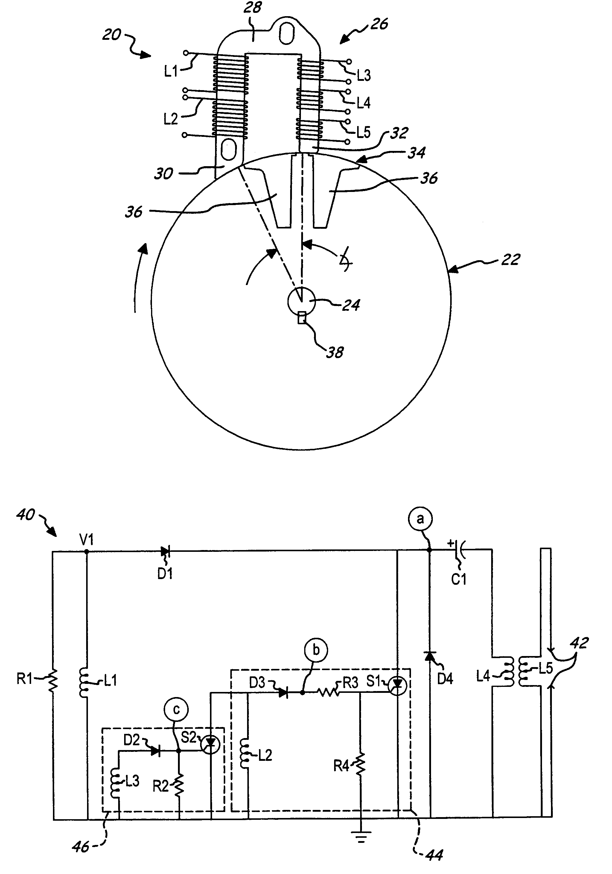
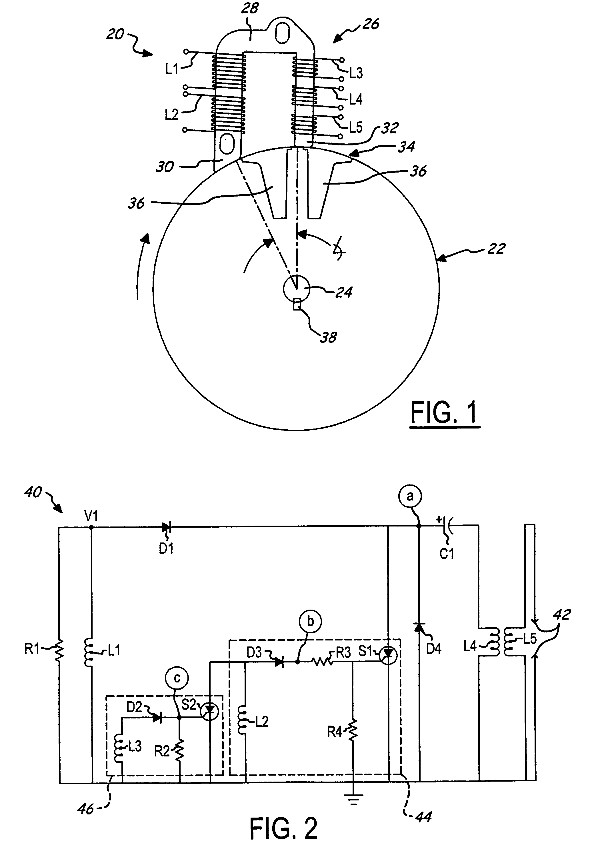
[0026]FIG. 2 illustrates a capacitor discharge ignition (CDI) circuit 40 in accordance with one presently preferred embodiment of the invention that, among other things, preferably enables starting of the engine at relatively low rotational crank speed. The circuit 40 will be described primarily in reference to FIG. 2, but also in reference to FIG. 1 at times. The CDI circuit 40 includes the ignition coil having the primary winding L4 and the secondary winding L5 coupled to a gap 42 of an ignition device or spark plug for initiating ignition spark in the engine.

[0027]The charge coil L1 has one end connected to electrical ground and another end in series through a diode D1, an ignition capacitor C1, and the primary winding L4 of the ignition coil. A resistor R1 is connected across the charge coil L1, and energy induced in the charge coil L1 during cranking at engine startup is used to charge the capacitor C1. The stored energy in the capacitor C1 is discharged into the primary windin...

second preferred embodiment

[0036]Skip-spark speed-governing may be provided with the present invention if desired. Referring now to FIG. 7, there is illustrated a CDI circuit 140 in accordance with an alternative embodiment of the present invention. The circuit 140 is substantially the same as the circuit 40 previously described with reference to FIG. 2, with the exception of two additional components—a capacitor C2 and a resistor R5 added to a timing sub-circuit 146. Therefore, the following discussion will focus primarily on the differences therebetween. The capacitor C2 is connected in parallel across the timing coil L3, such that the capacitor C2 is operatively connected to the gate of the SCR S2. The resistor R5 is connected in series with the resistor R2 across the capacitor C2, between the capacitor C2 and the gate of the SCR S2. Thus, the combination of the resistors R2, R5 and the capacitor C2 forms an RC network to control the operation of the SCR S2.

[0037]In operation, as long as engine speed remai...

third preferred embodiment

[0038]In addition to the speed governing function of the previously described circuit, a timing retard function may be provided for excessively high engine speed operation, if desired. Referring now to FIG. 8, there is illustrated a CDI circuit 240 in accordance with another alternative embodiment of the present invention. The circuit 240 is substantially the same as the circuit 140 previously described with reference to FIG. 7, with the exception of two components—a transistor T1 (in place of SCR S2) and a resistor R6 added to a timing sub-circuit 246. Therefore, the following discussion will focus primarily on the differences therebetween. The transistor T1 has a control electrode or base connected to the junction of the resistors R2, R5 and primary current conducting electrodes (collector and emitter) connected across the trigger coil L2. The resistor R6 is connected in series with the transistor T1 between the transistor T1 and the trigger coil L2.

[0039]In operation, as long as ...


PUM


Abstract

A capacitor discharge ignition (CDI) system includes a trigger circuit that generates a trigger signal in synchronism with operation of an engine for discharging an ignition capacitor. A timing circuit is connected to the trigger circuit for controlling the timing of the trigger signal and includes a timing coil for generating a timing signal in synchronism with operation of the engine. The timing circuit further includes a switch that has primary electrodes connected to the trigger circuit and a control electrode coupled to the timing coil for shorting the trigger circuit as a function of engine speed. The CDI system is thus capable of advancing engine timing to enable low-speed startup. The timing circuit is further adaptable to provide skip-spark speed-governing, timing retard speed-governing, and anti-reverse rotation of the engine.

Description

FIELD OF THE INVENTION[0001]This invention relates generally to ignition systems and more particularly to capacitor discharge ignition systems for internal combustion engines.BACKGROUND OF THE INVENTION[0002]Capacitor discharge ignition (CDI) systems are widely used in spark-ignited internal combustion engines. Generally, CDI systems include a main capacitor, which during each cycle of an engine, is charged by an associated generator or charge coil and is later discharged through a step-up transformer or ignition coil to fire a spark plug. CDI systems typically have a stator assembly including a ferromagnetic stator core having wound thereabout the charge coil and the ignition coil with its primary and secondary windings. A permanent magnet assembly is typically mounted on an engine flywheel to generate current pulses within the charge coil as the permanent magnet is rotated past the ferromagnetic stator core. The current pulses produced in the charge coil are used to charge the mai...

Claims


Application Information

Patent Timeline
Patent Type & Authority Patents(United States)
IPC IPC(8): F02P1/08F02P1/00F02P3/06F02P3/00F02P3/08F02P11/02
CPCF02P1/083F02P3/0807
Inventor KOLAK, LEWIS M.LAMARR, JR., GERALD J.
Owner WALBRO ENGINE MANAGEMENT
Why Eureka
Try Eureka