Fluid treatment elements

a treatment element and crossflow technology, applied in the direction of liquid degasification, separation processes, dissolving, etc., can solve the problems of unsuitability for situations, unsuitable for situations, and the fluid treatment system employing a crossflow fluid treatment element is usually more complicated, and achieves the effect of increasing the lifespan of the fluid treatment element, reducing the number of problems, and effective space us

Inactive Publication Date: 2005-08-23
PALL CORP
View PDF56 Cites 73 Cited by
  • Summary
  • Abstract
  • Description
  • Claims
  • Application Information

AI Technical Summary

Benefits of technology

[0042]The numerous advantages of the various above-mentioned and other aspects of the present invention will be described in detail below. Among these advantages are versatility permitting various modes of operation, high efficiency, effective use of space, and an increased lifespan of fluid treatment elements.

Problems solved by technology

For these reasons, a fluid treatment system employing a crossflow fluid treatment element is usually more complicated than one employing a dead end fluid treatment element and may be unsuitable for situations in which it is desired to treat small volumes of fluid at low flow rates.
Furthermore, in the treatment of fluids, for example, in the dissolution of or removal of gases in liquids, certain problems are encountered.
Such solutions are unfit for certain applications that require stringent purity, for example, in the manufacturing of semiconductors.
The fluids considered for cleaning of the silicon wafer, particularly corrosive or active fluids such as ozonated water, ozonated sulfuric acid, or aqueous solutions of hydrofluoric acid, when prepared by conventional methods contain bubbles that may adhere to the wafer and adversely affecting the quality or performance of the semiconductor.
Further, such conventional methods, as they operate on a sparging mode, provide rather low or inefficient gas to liquid transfer or dissolution rates.

Method used


Image

  • Fluid treatment elements
  • Fluid treatment elements
  • Fluid treatment elements

Examples


example 1

[0413]This Example illustrates an advantage of fluid treatment elements in particular, fluid treatment elements in accordance with an embodiment of the present invention, namely, that the fluid treatment elements provide superior performance when cleaning is carried out in the crossflow mode.

[0414]Two fluid treatment elements were subjected to repeated cycles of filtering followed by cleaning either by conventional backwashing or by crossflow cleaning using water in conjunction with air. Each fluid treatment element measured about 20 inches long and had a fluid treatment medium with a surface area of about 12 square feet per side. The two fluid treatment elements had similar fluid treatment layers, drainage layers, and flow rate per unit area. The fluid treatment element subjected to crossflow cleaning had the structure shown in FIG. 5. The fluid treatment element subjected to backwashing was similar in overall structure, except that it had a core which was perforated over its entir...

example 2

[0417]This Example illustrates a method of mass transfer in accordance with an embodiment of the present invention.

[0418]An all fluoropolymer pleated fluid treatment element substantially depicted in FIG. 23 comprising an expanded PTFE membrane of pore rating 0.2 μm and a PFA mesh was tested for transfer of ozone from a mixture of ozone and oxygen into deionized water. Two different ozone concentrations in oxygen, 150 g / m3 and 250 g / m3, were employed. The tests were carried out in single pass mode. The water flow rate was varied from 4 lpm to 16 lpm. The water pressure was 25 psi. The oxygen pressure was 20 psi. The concentration of ozone in water was monitored. FIG. 24 depicts the dissolved ozone concentration as a function of the water flow rate for the two ozone gas concentrations. As can be seen from the figure, the higher the gas phase ozone concentration, the higher the dissolved concentration. FIG. 24 also depicts the ozone flux as a function of the water flow rate. As can be...

example 3

[0419]This Example illustrates an advantage of the diffusive mass transfer in accordance with an embodiment of the present invention.

[0420]Two all fluoropolymer pleated fluid treatment element substantially depicted in FIG. 23 comprising an expanded porous PTFE membrane of pore rating 0.1 μm available from Pall Corporation as EMFLON™ and a diamond shaped PTFE mesh were tested in sparging and non-sparging modes. It was found that the testing in the non-sparging mode produced higher ozone transfer to water than in the sparging mode. Two different ozone concentrations were employed in these tests.

[0421]For the test where the O3:O2 concentration was 150 g / m3 and the ozone was sparged, the test conditions were as follows: Water flow rate, 8 lpm; oxygen flow rate, 4 slpm; P(water in), 28 psi; P(water out), 25 psi; P(oxygen in), 26 psi; P(oxygen out), 24-26 psi; recirculation volume, 8 gallons. The water temperatures were as follows: at the beginning of the test, 57.6° F., and at the end o...


PUM

PropertyMeasurementUnit
sizeaaaaaaaaaa
widthaaaaaaaaaa
diameteraaaaaaaaaa

Abstract

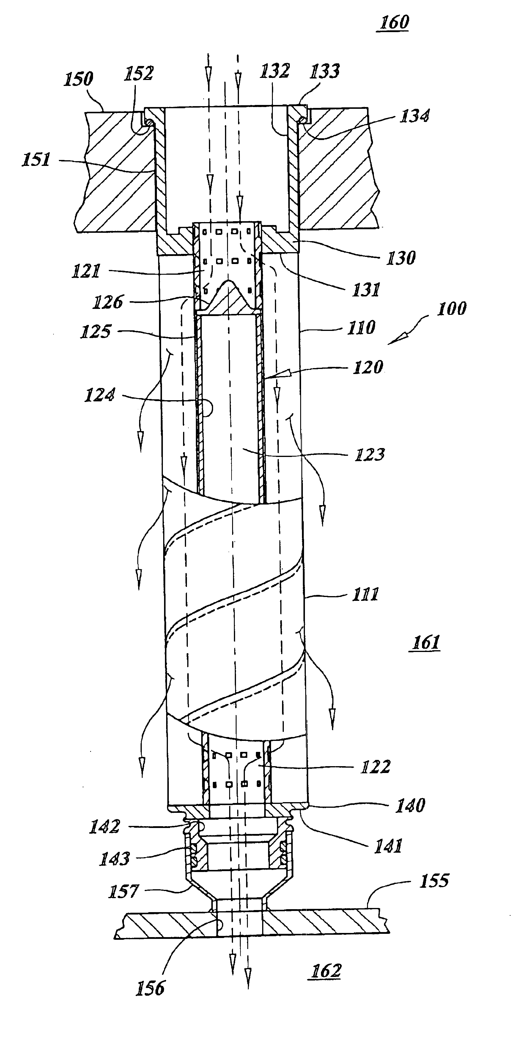
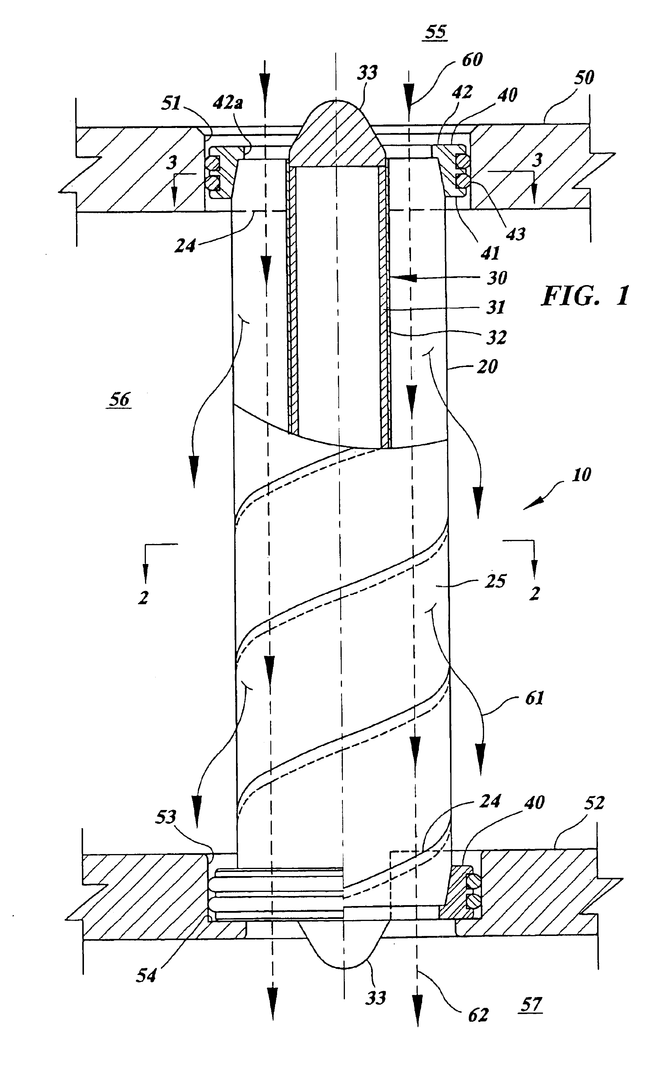
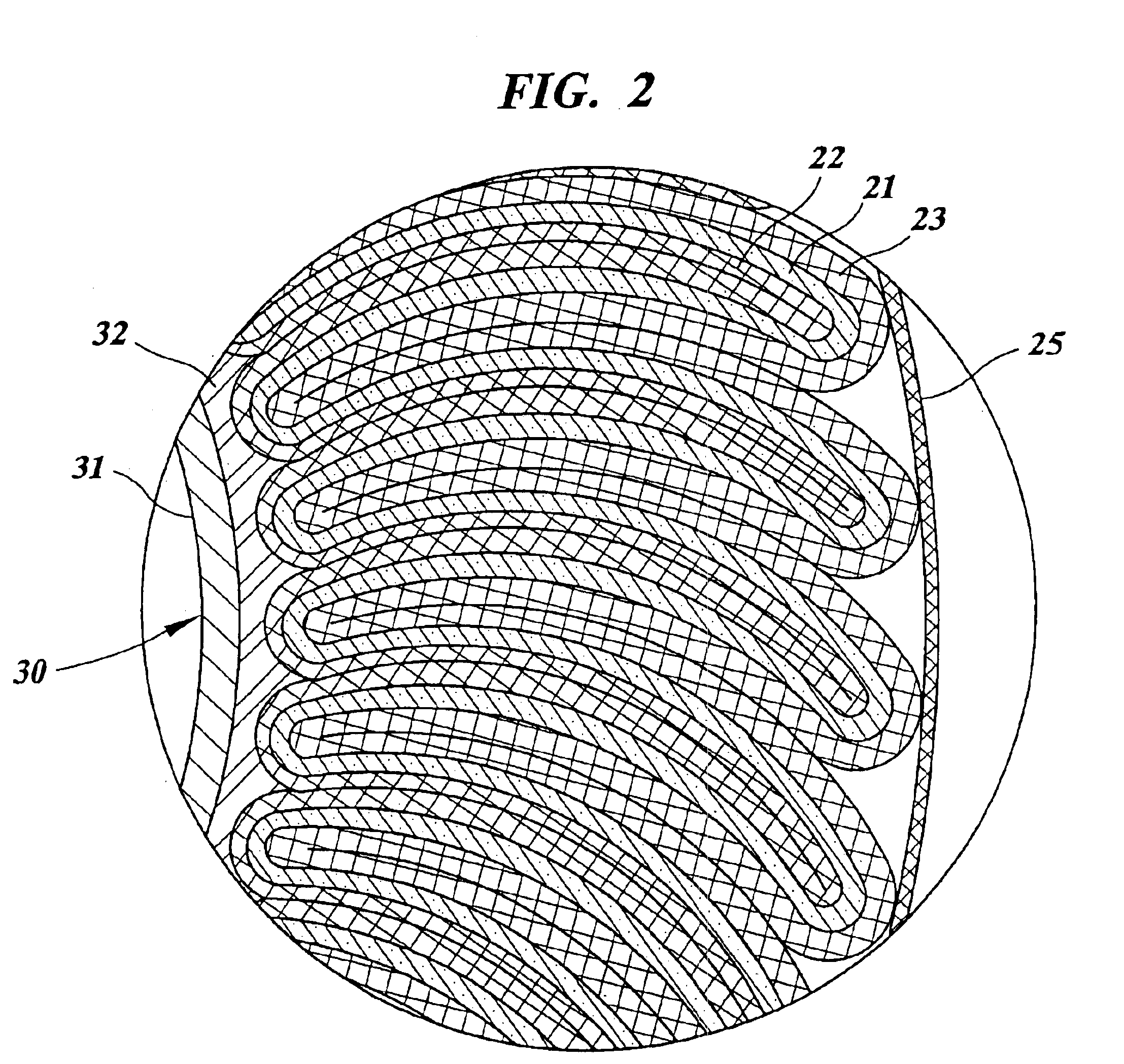
A fluid treatment element comprises a fluid treatment pack including a fluid treatment medium. The fluid treatment pack has a hollow interior and a barrier is disposed in the hollow interior. The barrier separates a blind region in which fluid cannot flow between the hollow interior and the fluid treatment pack from an open region in which fluid can flow between the hollow interior and the fluid treatment pack and prevents fluid from flowing between the blind region and the open region. The fluid treatment pack also has an end region having a sealed end. The fluid treatment element defines a flow path for process fluid to be treated passing in a lengthwise direction through a portion of the fluid treatment pack.

Description

CROSS-REFERENCE TO A RELATED APPLICATION[0001]This application is a divisional of copending U.S. patent application Ser. No. 09 / 786,724, filed Jul. 5, 2001, now issued as U.S. Pat. 6,702,941, which is a 371 of PCT / US99 / 20509 filed Sep. 9, 1999, which claims the benefit of U.S. Provisional patent application No. 60 / 099,663, filed Sep. 9, 1998.FIELD OF THE INVENTION[0002]The present invention generally relates to a fluid treatment element and fluid treatment methods such as filtering and material transfer from one fluid to another, and particularly to a filter element which is capable of operating in both a dead end mode and a crossflow mode. The present invention also relates to a method of cleaning the fluid treatment element.BACKGROUND OF THE INVENTION[0003]In one conventional type of fluid treatment known as dead end treatment, a fluid to be treated is introduced into a fluid treatment element, and the entirety or substantially all of the fluid is passed through a fluid treatment ...

Claims


Application Information

Patent Timeline
Patent Type & Authority Patents(United States)
IPC IPC(8): B01D25/00B01D33/00B01D35/14B01D35/157B01D61/00B01D19/00B01D29/07B01D29/11B01D29/50B01D29/66B01D46/24B01D46/52B01D53/22B01D53/78B01D63/00B01D63/06B01D63/08B01D63/10B01D63/14B01D71/36B01F1/00B01F5/06C02F1/50C02F1/76
CPCB01D46/0013B01D46/005B01D46/2411B01D46/522B01D53/78B01D53/22
Inventor HAQ, TANWEERMILLER, JOHN D.GEIBEL, STEPHEN A.ACQUAVIVA, JAMES
Owner PALL CORP
Why Eureka
Try Eureka