
Optical information recording medium and its manufacturing method

a technology of optical information and recording medium, which is applied in the field of optical information recording medium, can solve the problems of heat-caused deformation, tilt change, and difficulty in using such methods

Inactive Publication Date: 2005-08-23
PANASONIC CORP
View PDF17 Cites 18 Cited by
  • Summary
  • Abstract
  • Description
  • Claims
  • Application Information

AI Technical Summary

Problems solved by technology

Thus an issue for improving productivity is how to reduce the film formation time of the first protective layer 22.
However, because there are large temperature rises on the film adhering surface of the sample with these methods, heat-caused deformation, that is, tilt change, can occur when the substrate is made of resins such as polycarbonate.
For example, the glass transition temperature of polycarbonate is 150° C., and because it is necessary that the substrate temperature not be raised above the glass transition temperature in order to prevent deformation, it is difficult to use such methods.

Method used


Image

  • Optical information recording medium and its manufacturing method
  • Optical information recording medium and its manufacturing method
  • Optical information recording medium and its manufacturing method

Examples


working examples

[0042]The following is a description of optical information recording media of the present invention using specific examples. The atomic concentrations in each of the Working Examples and Comparative Examples were measured using Rutherford backscattering spectrometry.

working examples 7 to 14

(2) Working Examples 7 to 14

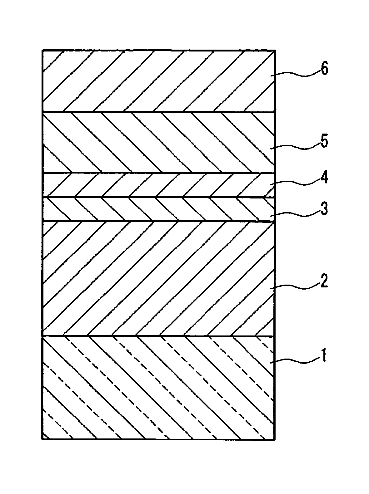
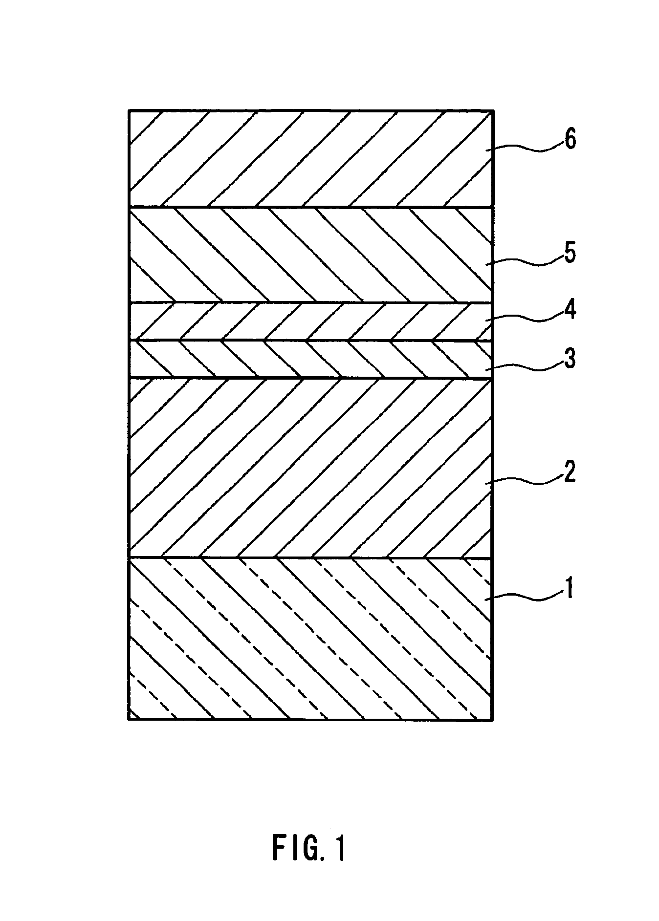
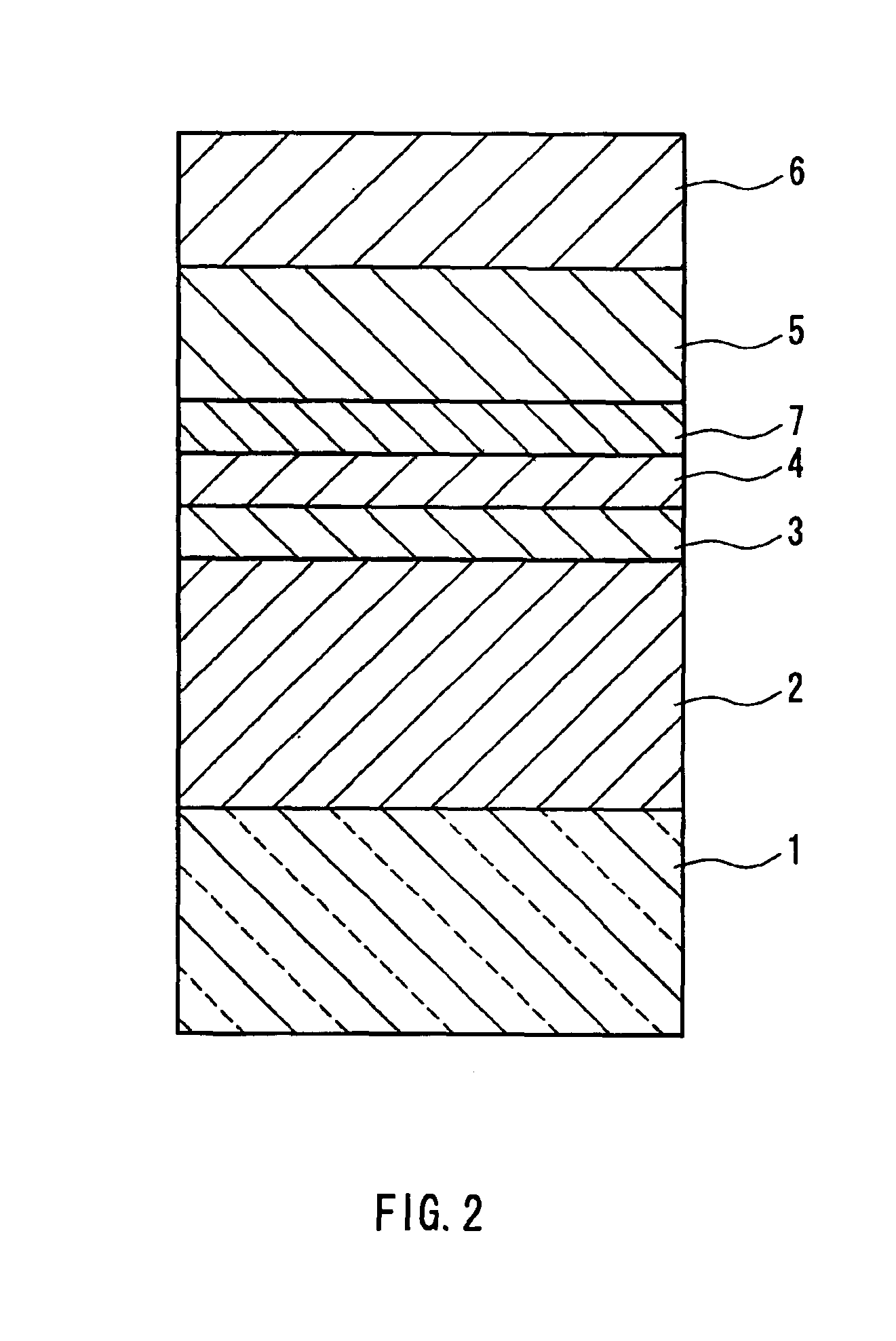
[0054]The optical disks used in the Working Examples 7 to 14 were given the same structure as that shown in FIG. 1. Furthermore, the substrate 1, the interface layer 3, the recording layer 4, the second protective layer 5, and the reflective layer 6 were manufactured in the same way as the optical disks of the Working Examples 1 to 6.

[0055]The first protective layers 2 included atoms of Zn, S, and Si, and were formed with a material that did not include atoms of O (the atomic composition ratio of O to Si was 0), and were respectively made so that, when the materials of the first protective layer 2 were expressed as (100-a) mol % ZnS-a mol % Si, a became 0 (Working Example 7), 3 (Working Example 8), 5 (Working Example 9), 10 (Working Example 10), 20 (Working Example 11), 30 (Working Example 12), 40 (Working Example 13), and 50 (Working Example 14), that is, the layers were made so that the amount of Si contained would become equivalent to these values. Fur...


PUM

PropertyMeasurementUnit
refractive indicesaaaaaaaaaa
mol %aaaaaaaaaa
mol %aaaaaaaaaa

Abstract

An optical information recording medium of the present invention includes a protective layer; an interface layer; and a recording layer, the optical characteristics of which are changed reversibly when irradiated by a laser beam, layered in this order on a substrate. The protective layer contains at least Zn, S, and Si atoms, and an atomic composition ratio of O to Si is at least 0 and smaller than 2. A refractive index of the interface layer is smaller than a refractive index of the protective layer.

Description

TECHNICAL FIELD[0001]The present invention relates to an optical information recording medium that is capable of recording information with high density and high speed by using optical means, and to a manufacturing method thereof.BACKGROUND ART[0002]Optical information recording media such as a magneto-optical recording medium and a phase-change recording medium are known for making it possible to record large amounts of data, and making it possible to reproduce and rewrite data at high-speeds. To record data, these optical information recording media take advantage of the differences in the optical characteristics of recording materials caused by localized irradiation by a laser beam. For example, a magneto-optical recording medium records data by taking advantage of the differences in the rotational angle of the plane of polarization of the reflected light that result from different states of magnetization. Also, a phase-change recording medium records data by taking advantage of ...

Claims


Application Information

Patent Timeline
Patent Type & Authority Patents(United States)
IPC IPC(8): G11B7/243G11B7/254G11B7/24G11B7/257G11B7/26G11B7/2403G11B7/24067G11B7/258
CPCG11B7/2403G11B7/24067G11B7/243G11B7/254G11B7/257G11B7/258Y10T428/21G11B2007/25706G11B2007/2571G11B2007/25711G11B2007/25713G11B2007/25716G11B7/26
Inventor OHTA, HIROYUKINAGATA, KEN'ICHI
Owner PANASONIC CORP
Learn More