Thermal barrier coating protected by thermally glazed layer and method for preparing same

a technology of thermally glazed layer and thermal barrier coating, which is applied in the field of thermal barrier coating, can solve the problems of partial (or complete) delamination and spalling of the coating, and achieve the effect of preventing the accumulation of cmas deposits in the porous surface structure of the thermal barrier coating, and reducing the build-up of cmas deposits

Inactive Publication Date: 2005-08-23
GENERAL ELECTRIC CO
View PDF33 Cites 50 Cited by
  • Summary
  • Abstract
  • Description
  • Claims
  • Application Information

AI Technical Summary

Benefits of technology

[0019]3. thermally melting the deposited thermally glazeable coating material so as to form a thermally glazed outer layer adjacent to and overlaying the inner layer and having an exposed surface, the thermally glazed outer layer having a thickness up to about 0.4 mils (10) microns and sufficient to at least partially protect the thermal barrier coating against environmental contaminants that become deposited on the exposed surface.
[0020]The thermal barrier coating of the present invention is provided with at least partial and up to complete protection and mitigation against the adverse effects of environmental contaminant compositions that can become deposited on the surface of such coatings during normal turbine engine operation. In particular, the thermal barrier coating of the present invention is p...

Problems solved by technology

As a result, these CMAS deposits are unable to cause undesir...

Method used


Image

  • Thermal barrier coating protected by thermally glazed layer and method for preparing same
  • Thermal barrier coating protected by thermally glazed layer and method for preparing same

Examples


Embodiment Construction

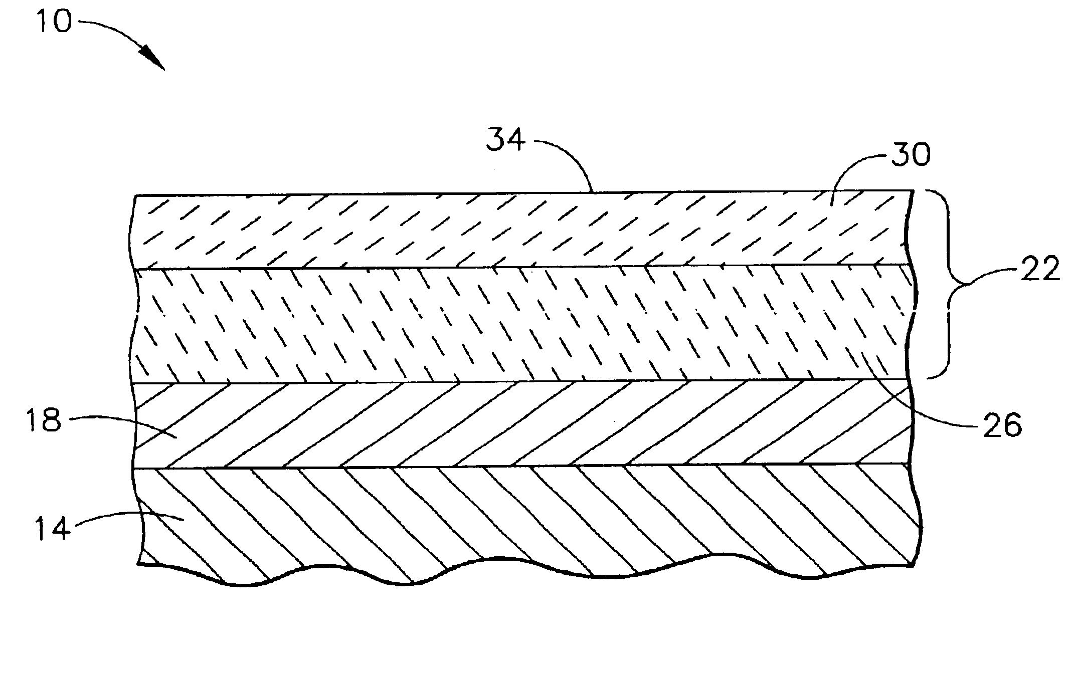
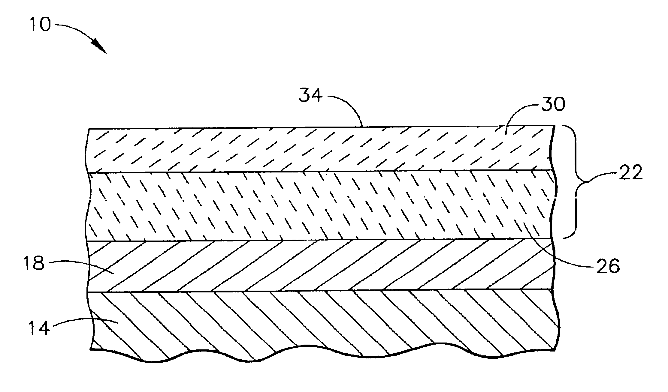
[0023]As used herein, the term “CMAS” refers environmental contaminant compositions that contain oxides of calcium, magnesium, aluminum, silicon, and mixtures thereof. These oxides typically combine to form compositions comprising calcium-magnesium-aluminum-silicon-oxide systems (Ca—Mg—Al—SiO).

[0024]As used herein, the term “ceramic thermal barrier coating materials” refers to those coating materials that are capable of reducing heat flow to the underlying metal substrate of the article, i.e., forming a thermal barrier and which having a melting point of at least about 2000° F. (1093° C.), typically at least about 2200° F. (1204° C.), and more typically in the range of from about 2200° to about 3500° F. (from about 1204° to about 1927° C.). Suitable ceramic thermal barrier coating materials for use herein include, aluminum oxide (alumina), i.e., those compounds and compositions comprising Al2O3, including unhydrated and hydrated forms, various zirconias, in particular chemically sta...


PUM

PropertyMeasurementUnit
Lengthaaaaaaaaaa
Lengthaaaaaaaaaa
Fractionaaaaaaaaaa

Abstract

A thermal barrier coating for an underlying metal substrate of articles that operate at, or are exposed to, high temperatures, as well as being exposed to environmental contaminant compositions. This coating comprises an inner layer nearest to the underlying metal substrate comprising a ceramic thermal barrier coating material having a melting point of at least about 2000° F. (1093° C.), as well as a thermally glazed outer layer having an exposed surface and a thickness up to 0.4 mils (about 10 microns) and sufficient to at least partially protect the thermal barrier coating against environmental contaminants that become deposited on the exposed surface, and comprising a thermally glazeable coating material having a melting point of at least about 2000° F. (1093° C.) in an amount up to 100%. This coating can be used to provide a thermally protected article having a metal substrate and optionally a bond coated layer adjacent to and overlaying the metal substrate. The thermal barrier coating can be prepared by forming the inner layer comprising the ceramic thermal barrier coating material, followed by depositing the thermally glazeable coating material on the inner layer, and then thermally melting the thermally glazeable coating material to form the thermally glazed outer layer.

Description

STATEMENT REGARDING FEDERALLY SPONSORED RESEARCH[0001]This invention was made with Government support under Contract No. N00019-96-C-0176 awarded by the Department of the Navy. The Government has certain rights to the invention.BACKGROUND OF THE INVENTION[0002]The present invention relates to thermal barrier coatings having a relatively thin thermally glazed surface layer for protection and mitigation against environmental contaminants, in particular oxides of calcium, magnesium, aluminum, silicon, and mixtures thereof that can become deposited onto such coatings. The present invention further relates to articles with thermal barrier coatings having such glazed surface layers and a method for preparing such coatings for the article.[0003]Thermal barrier coatings are an important element in current and future gas turbine engine designs, as well as other articles that are expected to operate at or be exposed to high temperatures, and thus cause the thermal barrier coating to be subjec...

Claims


Application Information

Patent Timeline
IPC IPC(8): C23C26/02C23C4/18C23C28/00F01D5/28
CPCC23C4/18C23C26/02F01D5/288C23C28/3215C23C28/345C23C28/36C23C28/3455Y10T428/24917Y10T428/12611Y10T428/24926Y10T428/26Y10T428/12618
Inventor NAGARAJ, BANGALORE ASWATHABOUTWELL, BRETT ALLENROCKSTROH, TODD JAYSCHEIDT, WILBUR DOUGLAS
Owner GENERAL ELECTRIC CO
Why Eureka
Try Eureka