Emitter turn-off thyristors (ETO)

Inactive Publication Date: 2005-08-23
VIRGINIA TECH INTPROP INC
View PDF2 Cites 59 Cited by
  • Summary
  • Abstract
  • Description
  • Claims
  • Application Information

AI Technical Summary

Benefits of technology

[0009]It is therefore an object of the present invention to provide an improved family of emitter turn-off

Problems solved by technology

Unfortunately, the gate can only be used to turn the device on, it cannot be used to turn the device off.
However, GTO's are known to have a poor turn off

Method used


Image

  • Emitter turn-off thyristors (ETO)
  • Emitter turn-off thyristors (ETO)
  • Emitter turn-off thyristors (ETO)

Examples


Embodiment Construction

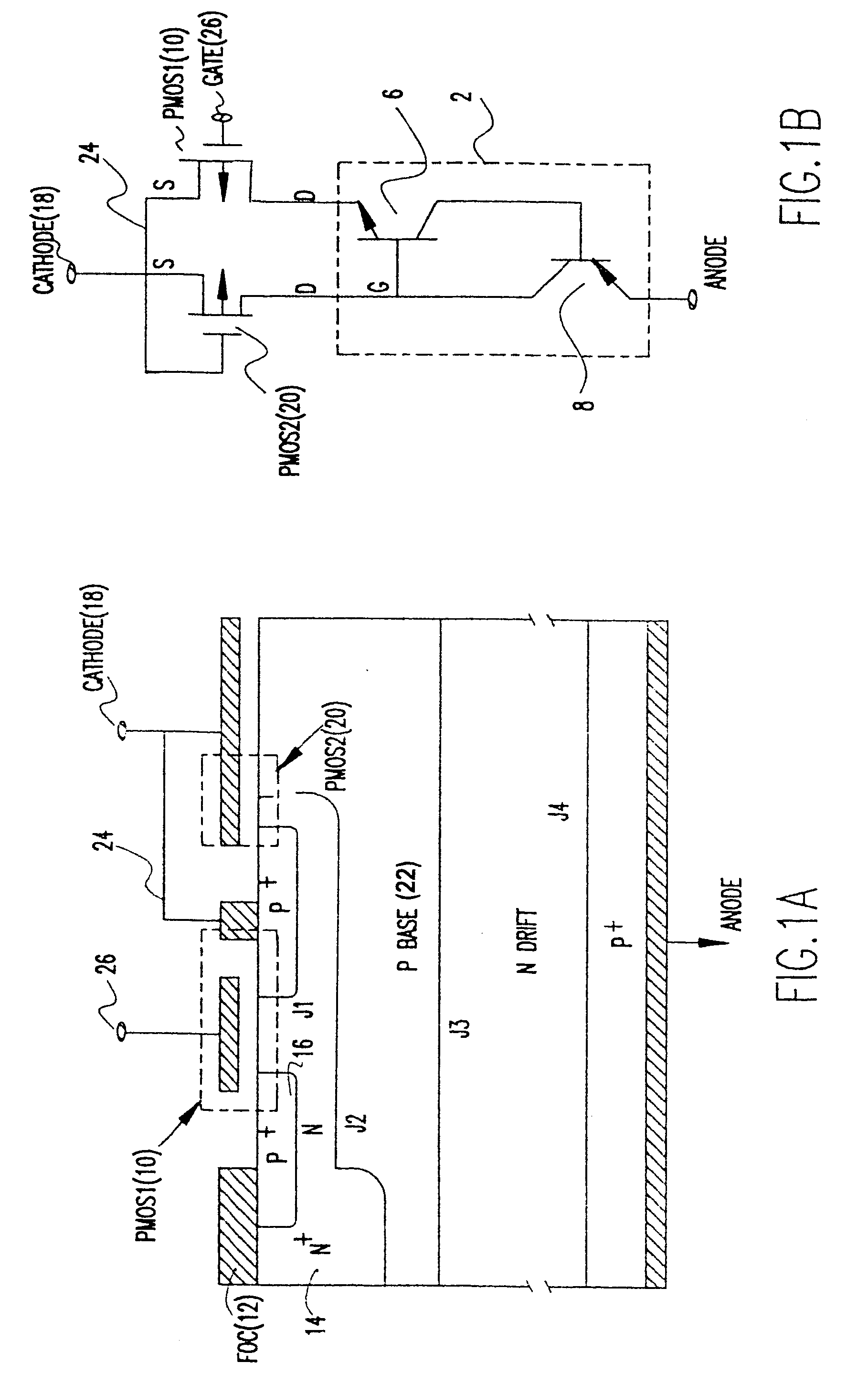
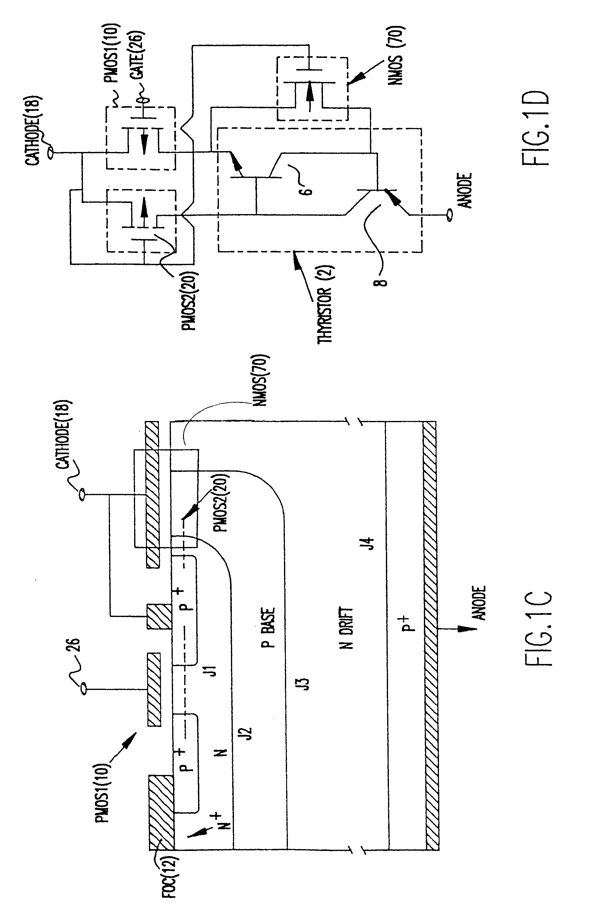
[0035]Referring now to the drawings, and more particularly to FIGS. 1A and 1B, there is shown a cross-sectional view of the emitter controlled thyristor (ECT) and its equivalent circuit, respectively. The ECT has a four-layer PNPN thyristor structure 2, in series with a P channel MOSFET (PMOS1) 10 integrated on the top N layer. In FIG. 1B the PNPN thyristor is shown as a PNP bipolar transistor 6 and NPN bipolar transistor 8. A Floating Ohmic Contact (FOC) 12 shorting the N emitter 14 and the P+ region 16 which acts as the source of the PMOS110. The FOC 12 provides the bridge for transferring emitter electron currents of the upper NPN transistor into hole currents, which then flow through the PMOS110 channel and into the cathode contact 18. A second PMOSFET (PMOS2) 20 is formed at the other side of the cathode contact with the upper P base 22 acting as the source. The PMOS2 does not have a separate control gate, instead, its gate 24 is tied to the cathode contact 18.

[0036]During the ...


PUM


Abstract

A family of emitter controlled thyristors employ plurality of control schemes for turning the thyristor an and off. In a first embodiment of the present invention a family of thyristors are disclosed all of which comprise a pair of MOS transistors, the first of which is connected in series with the thyristor and a second which provides a negative feedback to the thyristor gate. A negative voltage applied to the gate of the first MOS transistor causes the thyristor to turn on to conduct high currents. A zero to positive voltage applied to the first MOS gate causes the thyristor to turn off. The negative feedback insures that the thyristor only operates at its breakover boundaries of the latching condition with the NPN transistor portion of the thyristor operating in the active region. Under this condition, the anode voltage VA continues to increase without significant anode current increase. Emitter turn-off (ETO) thyristor fabrication packages are also disclosed having packaged semiconductor devices controlling the thyristor.

Description

[0001]This application is the national phase of PCT International Application No. PCT / US98 / 20594 filed on Sep. 30, 1998 under 35 U.S.C. § 371. This application also claims priority of provisional Application No. 60 / 060,557 filed in United States on Sep. 30, 1997.BACKGROUND OF THE INVENTION[0002]1. Field of the Invention[0003]The present invention generally relates to a novel family of thyristors and, more particularly, to a family of low cost metal oxide semiconductor (MOS) emitter turn-off thyristors.[0004]2. Description of the Prior Art[0005]Thyristors, sometimes referred to as silicon controlled rectifiers, are four layer pnpn devices comprising an anode, a cathode, and a gate terminal. Thyristors are designed to carry very high currents with very little voltage drop. For example, at currents of up to 500 A, the voltage drop across the anode and cathode terminals typically does not exceed 2 V. This makes thyristors ideal for power electronics switching applications such as conver...

Claims


Application Information

Patent Timeline
IPC IPC(8): H01L29/74H01L31/111H01L29/66H01L31/101H01L23/48H01L29/417H01L29/744H01L29/745H03K17/04H03K17/567
CPCH01L24/72H01L29/41716H01L29/7436H01L29/744H01L29/7455H03K17/0406H03K17/567H01L2924/1305H01L2924/1301H01L2924/01033H01L2924/01015H01L2924/01029H01L2924/13091H01L2924/19041H01L2924/30105H01L2924/30107H01L2924/3011H01L2924/01005H01L2924/01006H01L2924/01019H01L2924/01023H01L2924/00H01L2924/13034H01L2924/12035
Inventor HUANG, ALEX Q.
Owner VIRGINIA TECH INTPROP INC
Why Eureka
Try Eureka