PWM-based measurement interface for a micro-machined electrostatic actuator

Inactive Publication Date: 2005-08-23
ANALOG DEVICES INC
View PDF12 Cites 72 Cited by
  • Summary
  • Abstract
  • Description
  • Claims
  • Application Information

AI Technical Summary

Benefits of technology

[0011]Embodiments of the present invention use time-multiplexing to separate the measurement period from the driving period, eliminating cross-talk between the drive and measurement signals.

Problems solved by technology

These earlier techniques were subject to the following disadvantages:1. Sensitivity to low-frequency amplifier noise, such as voltage offset and 1 / f noise.2. Sensitivity to capacitive “feed-through” of the drive signal into the measurement signal.
Such pick-up is known as feed-through and is a form of noise.
This noise may be significant since prior art capacitive sensing systems provide only a small amount of current for capacitive sensing.3. Non-linear actuation force.4. Analog interface.
An analog interface adds to the complexity of the control circuitry.

Method used


Image

  • PWM-based measurement interface for a micro-machined electrostatic actuator
  • PWM-based measurement interface for a micro-machined electrostatic actuator
  • PWM-based measurement interface for a micro-machined electrostatic actuator

Examples


Embodiment Construction

[0017]It will be clear to one skilled in the art that the above embodiment may be altered in many ways without departing from the scope of the invention.

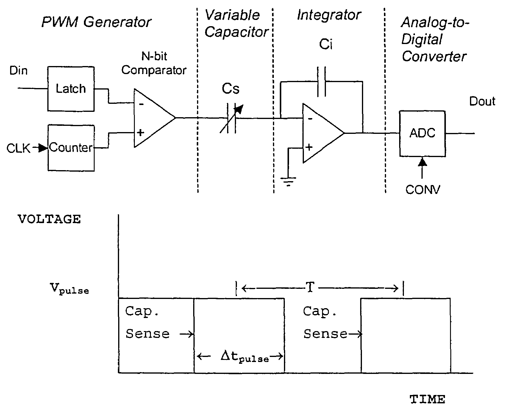
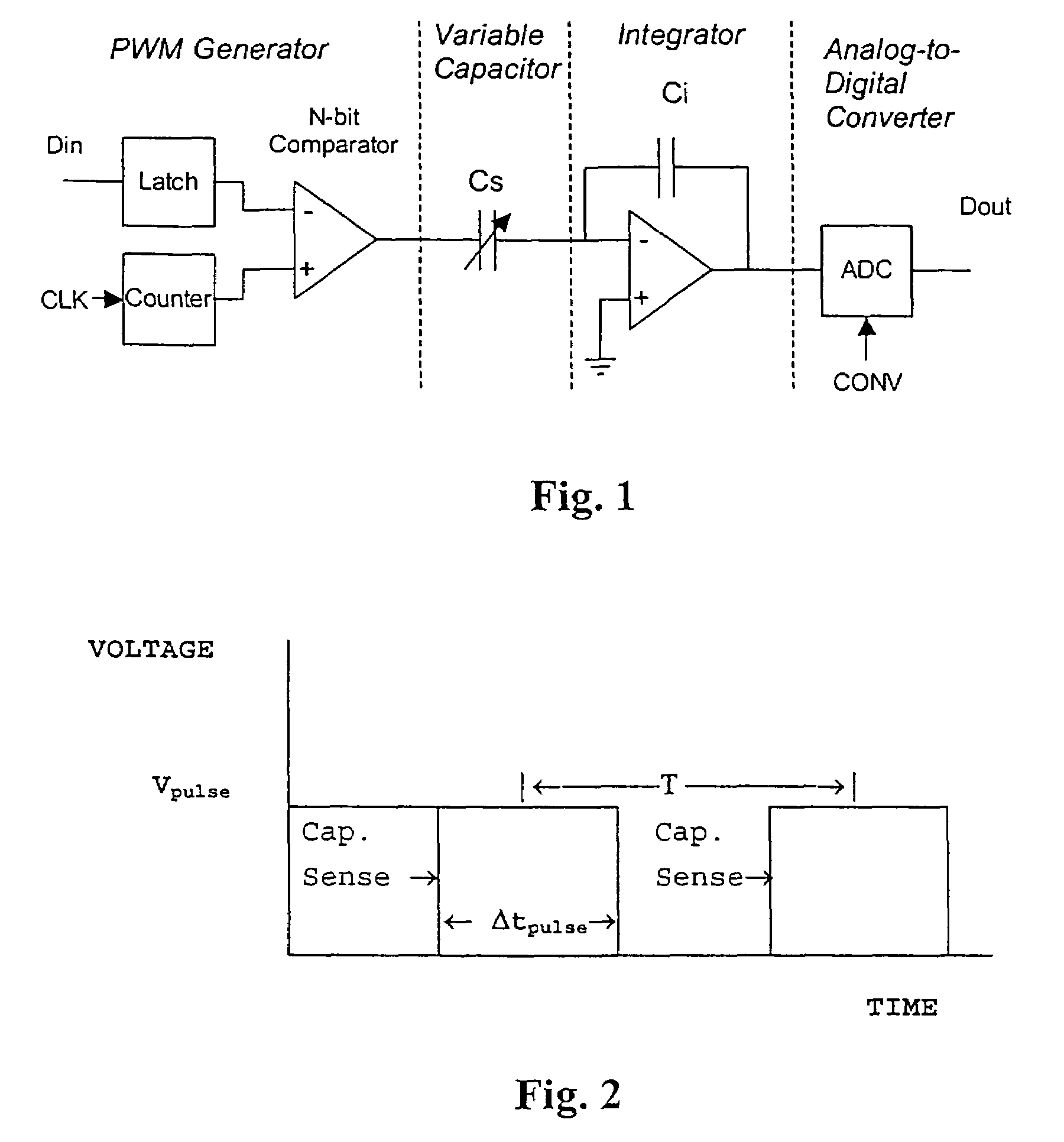
[0018]A circuit diagram according to an embodiment of the invention is illustrated in FIG. 1. The circuit consists of four stages—a pulse width modulation generator PWM, a MEMS device, represented as a variable sensor capacitor Cs, an integrator, and an analog-to-digital converter ADC. In the circuit, an input digital word Din is first converted into a PWM pulse train by the PWM generator. The voltage pulse train includes one or more pulses characterized by a pulse width Δtpulse. The voltage pulse train is applied to a MEMS device, represented in FIG. 1 as a variable sensor capacitor, Cs, and the resulting current is integrated across an integrator having a capacitance Ci. The amplitude of the pulse train output from the integrator is simply the amplitude of the input pulse train scaled by the ratio of the sensor capacitance to the ...


PUM


Abstract

Methods and apparatus for varying and measuring the position of a micromachined electrostatic actuator using a pulse width modulated (PWM) pulse train are disclosed. One or more voltage pulses are applied to the actuator. In each of the pulses, a voltage changes from a first state to a second state and remains in the second state for a time tpulse before returning to the first state. The position of the actuator may be varied by varying the time Δtpulse. A position of the actuator may be determined by measuring a capacitance of the actuator when the voltage changes state, whether the time t is varied or not. An apparatus for varying the position of a MEMS device may include a pulse width modulation generator coupled to the MEMS device an integrator coupled to the MEMS device and an analog-to-digital converter coupled to the integrator. The integrator may measure a charge transferred during a transition of a pulse from the pulse generator. The integrator may include an amplifier, an integrator capacitor, a hold capacitor, a compensation voltage generator and three switches. The hold capacitor and integrator capacitor may be coupled to a MEMS device. The integrator capacitor, hold capacitor, and compensation voltage generator may be selectively coupled to the amplifier by two of the switches. The MEMS device and hold capacitor may be selectively coupled to ground by a third switch.

Description

CROSS-REFERENCE TO A RELATED APPLICATION[0001]The present application is a continuation of U.S. patent application Ser. No. 10 / 012,688 (now U.S. Pat. No. 6,674,383) filed Oct. 30, 2001, which is based on and claims priority from Provisional application 60 / 245,249 filed Nov. 1, 2000, the entire disclosure of both of which are incorporated herein by reference.FIELD OF THE INVENTION[0002]This invention relates generally to microelectromechanical system (MEMS) devices. More particularly, it relates to actuating and measuring the motion of a micro-machined electrostatic actuator.BACKGROUND OF THE INVENTION[0003]Prior methods for capacitive position sensing of MEMS devices have been focused towards inertial sensors such as accelerometers and gyroscopes. These earlier techniques were subject to the following disadvantages:[0004]1. Sensitivity to low-frequency amplifier noise, such as voltage offset and 1 / f noise.[0005]2. Sensitivity to capacitive “feed-through” of the drive signal into the...

Claims


Application Information

Patent Timeline
IPC IPC(8): G01R31/28H02N1/00
CPCG01R31/2829H02N1/002
Inventor HORSLEY, DAVIDCONANT, ROBERTCLARK, WILLIAM
Owner ANALOG DEVICES INC
Why Eureka
Try Eureka