Contoured piston

Inactive Publication Date: 2005-08-30
BENDIX COMML VEHICLE SYST LLC
View PDF10 Cites 18 Cited by
  • Summary
  • Abstract
  • Description
  • Claims
  • Application Information

AI Technical Summary

Benefits of technology

[0007]These and other limitations of the prior art are overcome by the present invention which provides a piston for use in (i) compressors, including air-brake compressors used with heavy duty freight vehicles such as trucks and buses, and (ii) internal combustion engines such as those used in a wide variety of motor vehicles. In the most generic sense, the present invention comprises a piston having a contoured body that includes a variety of features that effectively reduce the oil pressure that typically builds just below the oil control ring when the piston is in operation. More specifically, this piston includes drainage notches, drainage furrows, drainage bores, channels and groove(s). These features function separately or together to reduce any excessive oil pressure by directing the oil away from the piston rings and back toward the crankcase of the engine or compressor.

Problems solved by technology

In any engine oil, the detergent-dispersant, anti-wear, oxidation, and rust and corrosion additives eventually become depleted and the oil loses much of its ability to prevent deposits from accumulating on critical engine parts.
Among the critical engine components affected by improperly maintained oil are the piston rings and the piston itself.
Hard, baked-on deposits formed from the contaminants in the oil may cause the rings to stick and lose their sealing ability, thereby allowing the oil to leak past the rings into the combustion chamber where it is burned.
Combustion of the engine's oil in this manner results in rapid oil deterioration, increased oil consumption, and is a source of contaminants that can reduce the effectiveness of the car's emission control devices.
Additionally, stuck piston rings cause a loss of power and allow combustion products (“blow-by”) to enter the crankcase, further contaminating the oil and accelerating its deterioration.
In addition to contaminants in the oil, recent studies of the oil film thickness of the piston rings in certain reciprocating compressors (see IMechE 2001 C591 / 013 / 20021) have suggested that a major factor negatively affecting oil consumption is insufficient or inadequate oil drainage by the piston itself.
The accumulation of excessive hydrodynamic pressure at the piston rings can force the rings into the grooves in an undesirable manner, thereby permitting an excessive amount of oil to pass through the rings' running faces.

Method used


Image

  • Contoured piston
  • Contoured piston
  • Contoured piston

Examples


Embodiment Construction

Reference Numerals

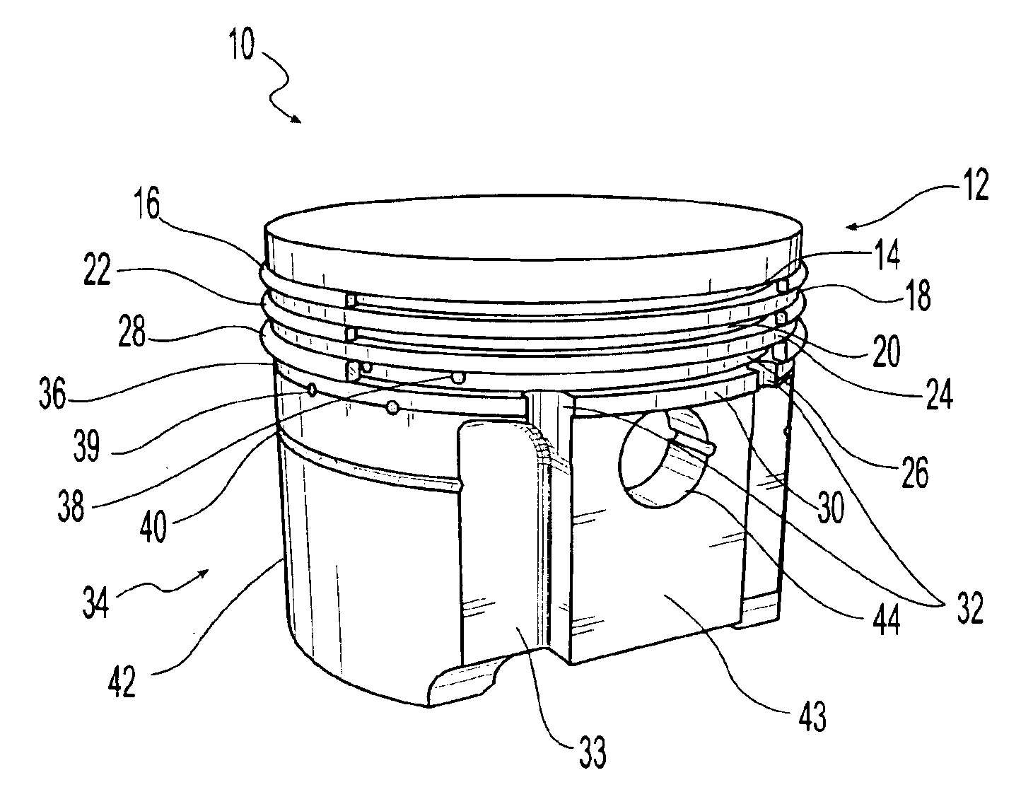
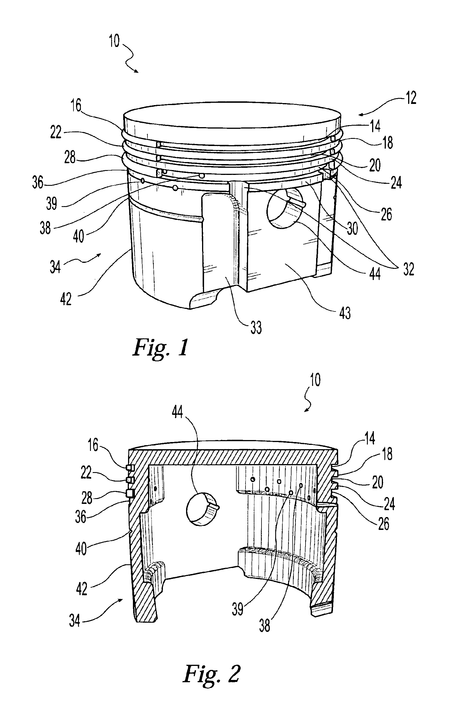
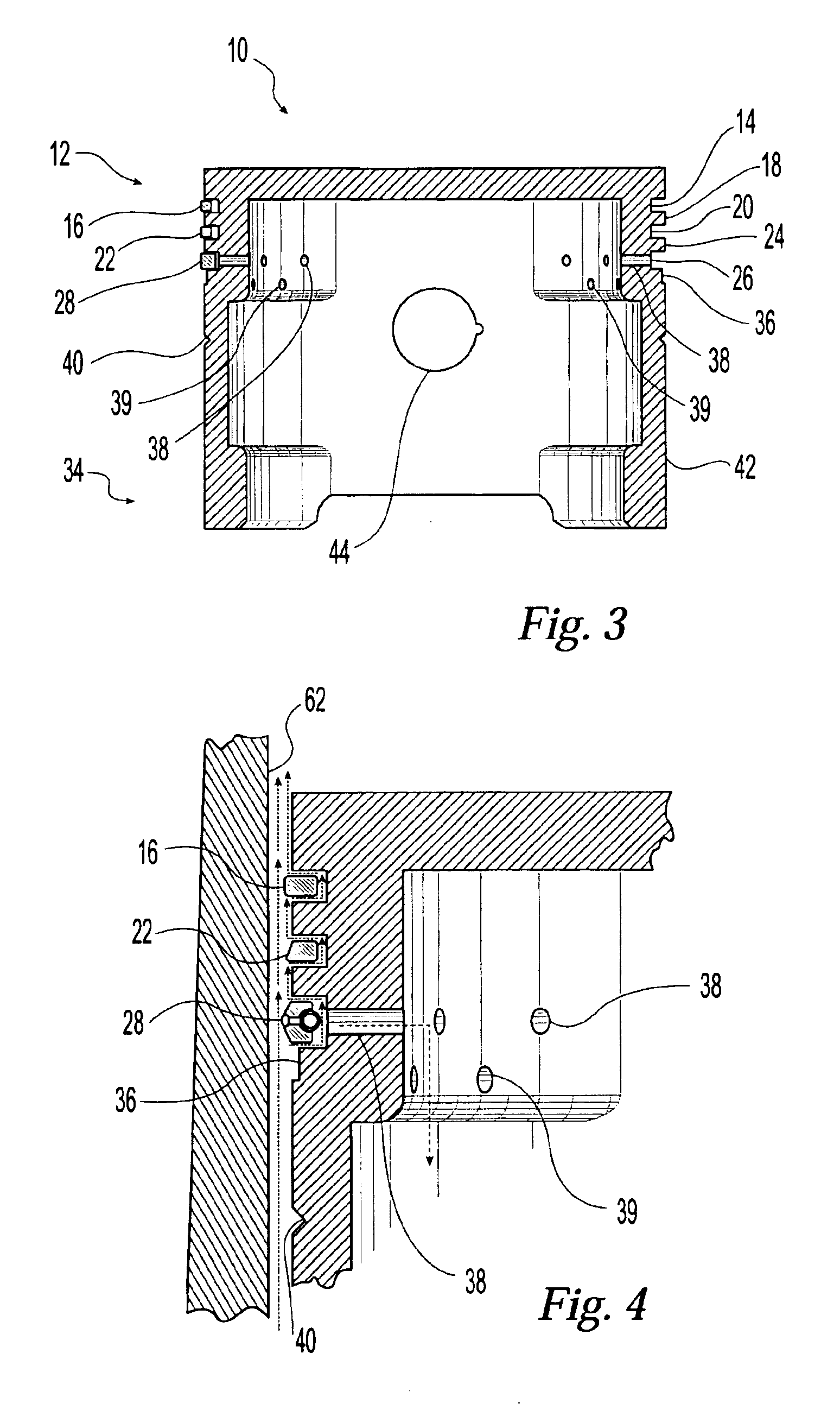
[0018]10 piston body[0019]12 piston crown[0020]14 first piston ring groove[0021]16 first piston ring (1st compression ring)[0022]18 first piston ring land[0023]20 second piston ring groove[0024]22 second piston ring (2nd compression ring)[0025]24 second piston ring land[0026]26 third piston ring groove[0027]28 third piston ring (oil control ring)[0028]30 third piston ring land[0029]32 drainage notches[0030]33 drainage furrows[0031]34 piston skirt[0032]36 channel (recessed surface area)[0033]38 first plurality of drainage bores[0034]39 second plurality of drainage bores[0035]40 groove[0036]42 outer skirt wall[0037]43 piston face[0038]44 piston pin aperture[0039]46 piston pin bore[0040]48 piston pin[0041]50 connecting rod[0042]52 crankshaft[0043]54 crankcase[0044]55 oil[0045]56 oil pan[0046]58 sump[0047]60 engine block[0048]62 cylinder[0049]64 combustion / compression chamber

[0050]With reference to the Figures, an exemplary embodiment of the present invention provides ...


PUM


Abstract

A piston for use in internal combustion engines or reciprocating compressors such as those utilized in air-brake systems for heavy duty freight vehicles. The body of the piston of the present invention is contoured in manner to reduce the undesirable build-up of oil pressure that frequently occurs at the oil control ring or rings when the piston is in operation. The crown portion of the piston body includes a series of piston ring groove and piston ring lands, one of which is modified to include drainage notches. The skirt portion of the piston body includes a plurality of furrows near the face of the piston, a horizontal channel recessed into the surface of the piston skirt, and a horizontal groove formed in the outer skirt wall of the piston. These structures function individually and in combination to provide multiple means by which excess lubricating oil may be directed away from the oil control rings and back toward the crankcase or oil reservoir within the engine or compressor.

Description

TECHNICAL FIELD OF THE INVENTION[0001]The present invention relates generally to pistons designed for use in reciprocating compressors and internal combustion engines, and specifically to pistons designed to reduce the oil pressure experienced by piston oil rings when the piston is in operation.BACKGROUND OF THE INVENTION[0002]A typical four-stoke internal combustion engine involves four piston strokes. The first stroke is the intake or suction stroke in which the piston moves down the cylinder and creates a partial vacuum in the cylinder. Intake air alone, or a mixture of air and fuel, is forced though the inlet valve into the cylinder by atmospheric pressure which is now greater than the pressure in the cylinder. During this stroke, the exhaust valve stays closed. The second stroke is the compression stroke wherein the piston moves up in the cylinder with both valves closed. The intake air or air and fuel mixture is compressed and the pressure inside the cylinder rises. The third ...

Claims


Application Information

Patent Timeline
IPC IPC(8): F02F3/00F16J1/09F16J9/20
CPCF02F3/00F16J1/09F16J9/206F01M1/00
Inventor DUNAEVSKY, VALERY V.ARIGA, SUSUMU
Owner BENDIX COMML VEHICLE SYST LLC
Why Eureka
Try Eureka