High-pressure fuel injection pipe having connecting head

a fuel injection pipe and connecting head technology, applied in the direction of hose connection, machine/engine, mechanical equipment, etc., can solve the problems of deteriorating seal performance, inability to obtain sufficient seal face pressure, and inability to wash or sleeve washer, so as to improve internal pressure fatigue strength, improve the effect of sealing performance and deteriorating mountability

Inactive Publication Date: 2005-08-30
USUI KOKUSAI SANGYO KAISHA LTD
View PDF19 Cites 24 Cited by
  • Summary
  • Abstract
  • Description
  • Claims
  • Application Information

AI Technical Summary

Benefits of technology

[0005]In the case of this high-pressure fuel injection pipe, by the action of the connecting washer 16 having the chamfered portion 16a to cover the outer circumference of the lower neck portion of the connecting head 12, the sharp wrinkle or pocket to be easily formed in the inner side of the head by the buckling work can be formed into an annular groove 18 having a shallow and gentle section. As a result, there is attained an effect to reduce the possibility of starting the fatigue failure due to the concentration of stress in the head.
[0007]The present invention has been conceived to solve the aforementioned problems of the high-pressure fuel injection pipe shown in FIG. 14, and has an object to provide a high-pressure fuel injection pipe, which has a connecting head for a high seal performance by preventing a washer or sleeve washer from being plastically deformed.
[0011]Specifically, the invention is given such a structure that the connecting washer to cover the outer circumference of the lower neck portion of the connecting head is provided with the stepped portion, and that the connecting head is provided on its back face with the stepped portion corresponding wholly or partially to the stepped portion of the connecting washer, so that the stepped portions may abut against each other. As a result, the wedge effect due to the slope can be eliminated to prevent the plastic deformation of the connecting washer (e.g., the washer or the sleeve washer) in the radially expanding direction so that the interference between the washer and the inner circumference of the box nut and the drop of the seal face pressure can be prevented to provide a high seal performance. Moreover, the annular groove (or the pocket) to be formed in the inner side of the head by the buckling work is also made shallow and gentle. Thus, the value of the stress to occur in the pocket at a high-pressure load time is lowered to improve the internal pressure fatigue strength.
[0013]The high-pressure fuel injection pipe according to the invention is given the structure, in which the stepped portion having no slope is formed on the back face of the connecting head and in which the stepped portion corresponding wholly or partially to the stepped portion of the connecting head is formed in the contact type connecting washer or fastening nut to cover the back face of the connecting head. As a result, the wedge effect due to the slope can be eliminated to prevent the plastic deformation of the connecting washer (e.g., the washer or the sleeve washer) or the fastening nut so that the interference between the sleeve washer and the inner circumference of the box nut and the drop of the seal face pressure can be prevented to provide a high seal performance. Moreover, the annular groove (or the pocket) to be formed in the inner side of the head by the buckling work is also made shallow and gentle thereby to eliminate the fear of cavitation erosion, as might otherwise be caused in the inner side of the head due to the hydraulic pressure. Another excellent effect is to reduce the possibility of starting the fatigue failure drastically. According to the results of our FEM (Finite Element Method) analyses, it has been found out that the high-pressure fuel injection pipe according to the invention can have an effect of a less residual stress in the pocket and a less strain in the inner surface than those of the high-pressure fuel injection pipe of the prior art.

Problems solved by technology

However, this high-pressure fuel injection pipe of the prior art having the connecting head is troubled by a problem that the deep and large annular sharp wrinkle or pocket 17 formed in the head establishes a point to start the fatigue failure due to the high-pressure fluid when the injection pipe is arranged for use.
In the aforementioned case of the high-pressure fuel injection pipe shown in FIG. 14, however, as the injection pressure rises to increase the axial force necessary for the sealing purpose, the washer or sleeve washer is easily deformed by the axial force thereby to raise a problem that a sufficient seal face pressure cannot be obtained.
As a result, the seal face pressure drops to degrade the seal performance.

Method used


Image

  • High-pressure fuel injection pipe having connecting head
  • High-pressure fuel injection pipe having connecting head
  • High-pressure fuel injection pipe having connecting head

Examples


Embodiment Construction

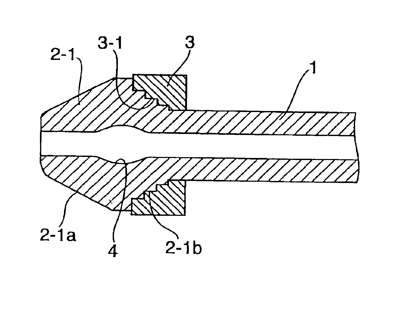
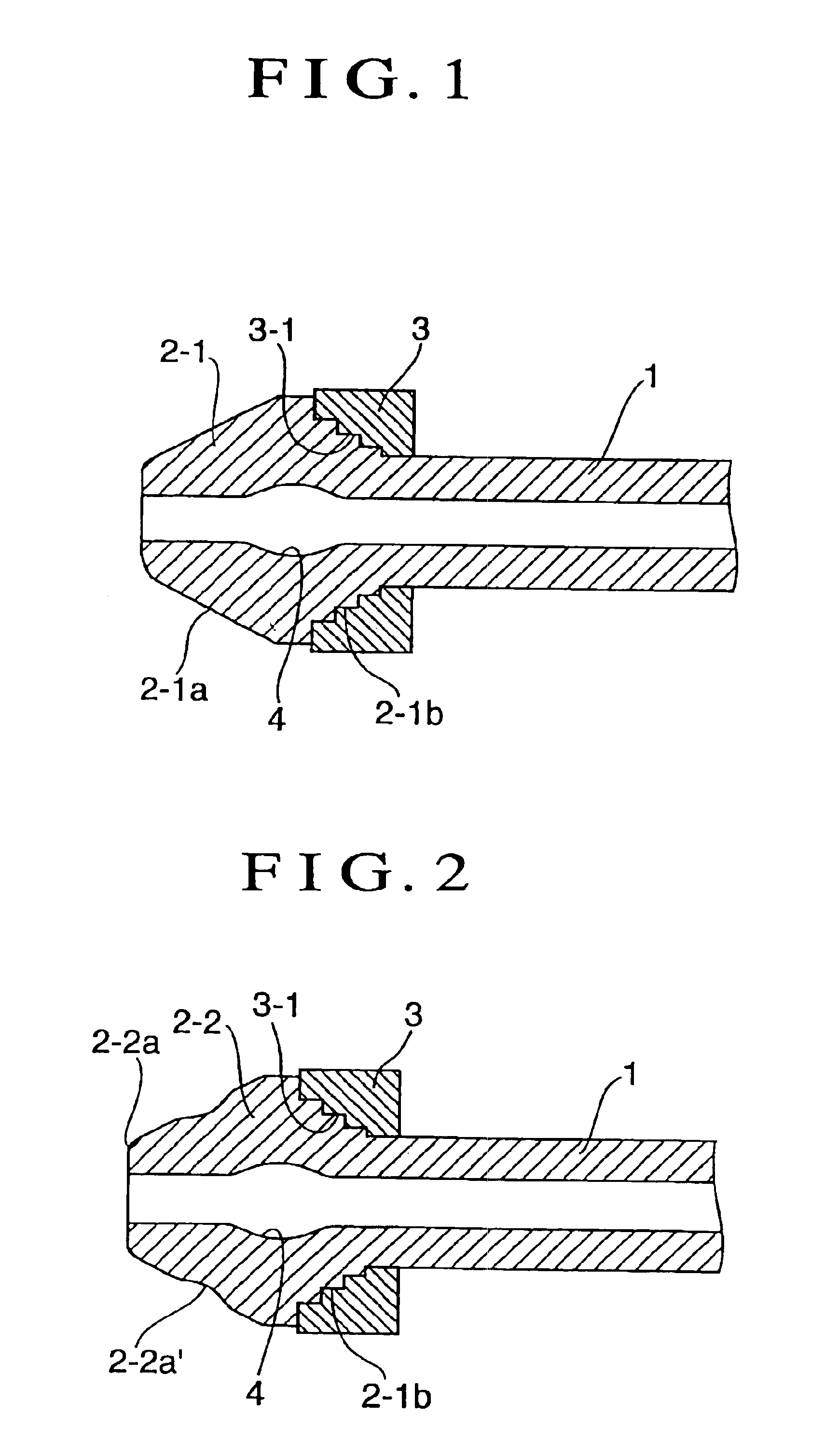
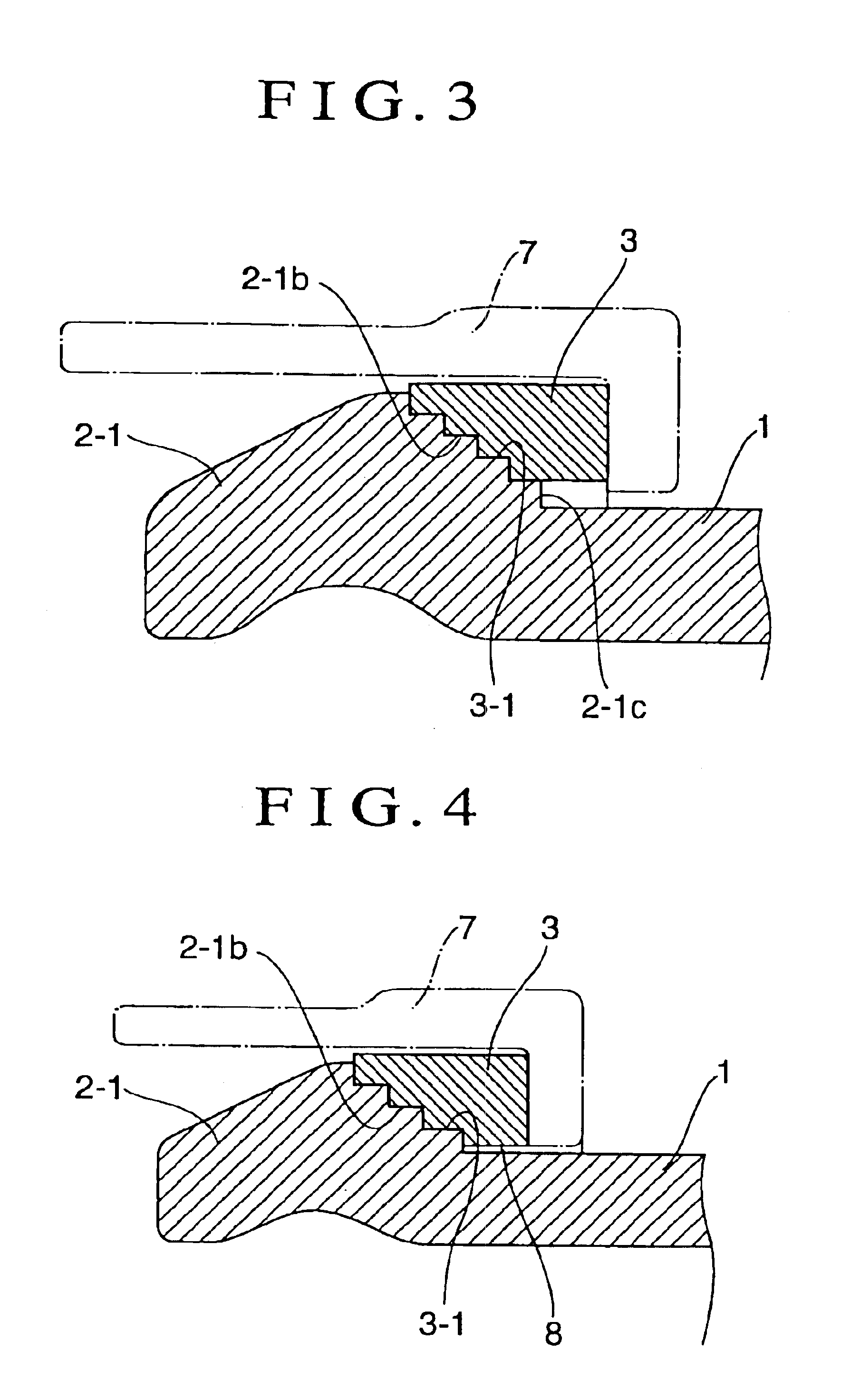
[0028]In FIG. 1 to FIG. 11: reference numeral 1 designates a thick steel pipe; numerals 2-1 and 2—2 a connecting head; numerals 2-1a and 2-2a a seat face; numeral 2-2a′ a curved groove; numerals 2-1b, 3-1, 3a-1, 3b-5, 3c-1 and 7a-1 a stepped portion; numerals 3, 3a and 3b a washer; numeral 3c a sleeve washer; numeral 4 an annular groove; numerals 5 and 15 a chuck; numeral 6 a punch member; numerals 7 and 7a a fastening nut; and numerals 8 and 8a a clearance.

[0029]The thick steel pipe 1 is formed of a relatively small-diameter thick tube, which is made of a carbon steel material or a stainless steel material precut to a predetermined size for the high-pressure fuel injection pipe and which has a diameter of about 4 mm to 20 mm and a thickness of about 1 mm to 8 mm.

[0030]The high-pressure fuel injection pipe shown in FIG. 1 is given such a structure that the thick steel pipe 1 is provided at its connecting end portion with the connecting head 2-1 having an outer circumference formed i...


PUM

PropertyMeasurementUnit
angle of inclinationaaaaaaaaaa
thicknessaaaaaaaaaa
diameteraaaaaaaaaa

Abstract

A high-pressure fuel injection pipe has a connecting head with an outer circumference formed for a mating seat portion. A shallow annular groove is formed in the inner side of the connecting head while shaping the head. A connecting washer is fit on the outer circumference of the lower neck of the connecting head. The injection pipe is characterized in that the lower neck of the connecting head is provided with an at least two-stepped portion having no slope, and in that the connecting washer is provided with a stepped portion corresponding at least partially to the stepped portion of the connecting head, so that the stepped portions may abut against each other.

Description

TECHNICAL FIELD[0001]The present invention relates to a high-pressure fuel injection pipe having a connecting head, which is frequently used as a fuel feed passage in a diesel engine, for example, and which has the connecting head made of a thick steel pipe having a relatively small diameter of 4 mm to 20 mm and a thickness of about 1 mm to 8 mm.BACKGROUND ART[0002]In the high-pressure fuel injection pipe having the connecting head of that kind in the prior art, as shown in FIG. 12 and FIG. 13, as a frustrum connecting head 12 having a seat face 13 formed of an outer circumference at the end portion of a thick steel pipe 11 is shaped by a buckling work to push it in the pipe axis direction from the outside with a punch member, a deep and large annular sharp wrinkle or pocket 17 is formed in the head inner circumference by the outward expansion accompanying the buckling work of the pushing operation. On the lower neck portion of the connecting head 12, on the other hand, there is fit...

Claims


Application Information

Patent Timeline
Patent Type & Authority Patents(United States)
IPC IPC(8): F02M55/00F16L19/02F16L19/028F02M55/02
CPCF02M55/005F16L19/0283F02M55/00
Inventor FURUGEN, MUNEKATSU
Owner USUI KOKUSAI SANGYO KAISHA LTD
Why Eureka
Try Eureka