High reliability precision latch

a high reliability, precision technology, applied in couplings, instruments, hoisting equipment, etc., can solve the problems of not meeting the needs of high rigidity, linearity, precision, and conventional latching technology for interlocking deployable space telescopes, and achieves high reliability, maintain mirror performance, and high stability.

Inactive Publication Date: 2005-08-30
EXCELIS INC
View PDF7 Cites 26 Cited by
  • Summary
  • Abstract
  • Description
  • Claims
  • Application Information

AI Technical Summary

Benefits of technology

[0007]The present invention has the following advantages: a high stability, high reliability, ball-in-cone type latch mechanism designed specifically for large deployable optical systems. The latch mechanism according to the present invention is well suited for use in the deployment of a segmented primary mirror comprising a plurality of petals surrounding a monolithic center segment. Additionally, the present invention provides a precision latch mechanism that can be used to interlock the metering structure of a segmented mirror, once the mirror is deployed to thereby maintain mirror performance. The precision latch mechanism according to the present invention has high repeatability along with linearity, stability, high stiffness and precision as a latch mechanism.

Problems solved by technology

The current state of the art has reached the practical size limit of monolithic mirrors.
Conventional latching technology, discussed in greater detail below, does not address the need for high stiffness, linearity, and precision in latches that are used for interlocking deployable space telescopes.
Furthermore, latch technology, as used in satellite antennae, does not meet optical tolerance requirements.
Satellite antennae latches often suffer from repeatability and stability problems that are typically two orders of magnitude below optical system requirements.

Method used


Image

  • High reliability precision latch
  • High reliability precision latch
  • High reliability precision latch

Examples


Embodiment Construction

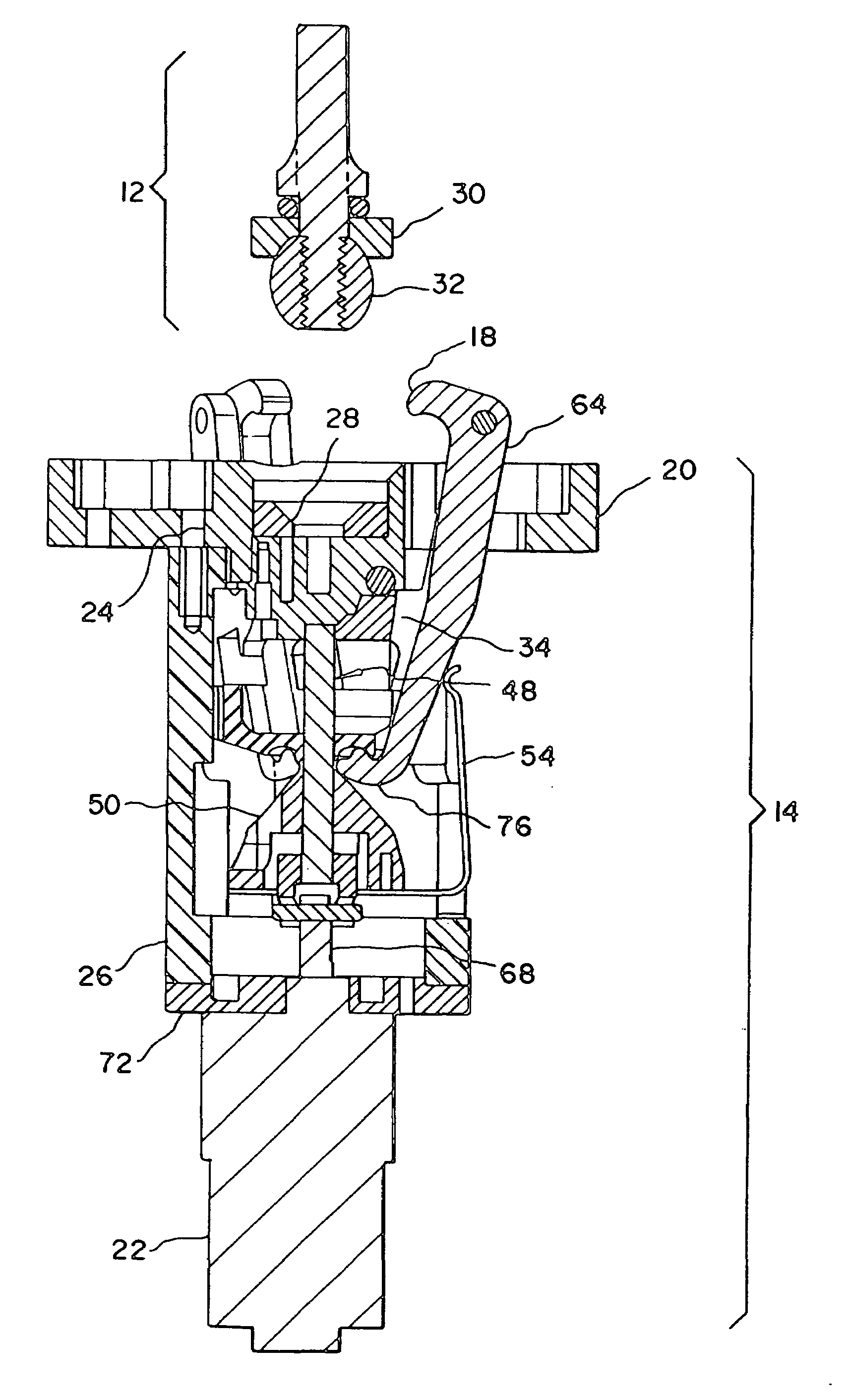
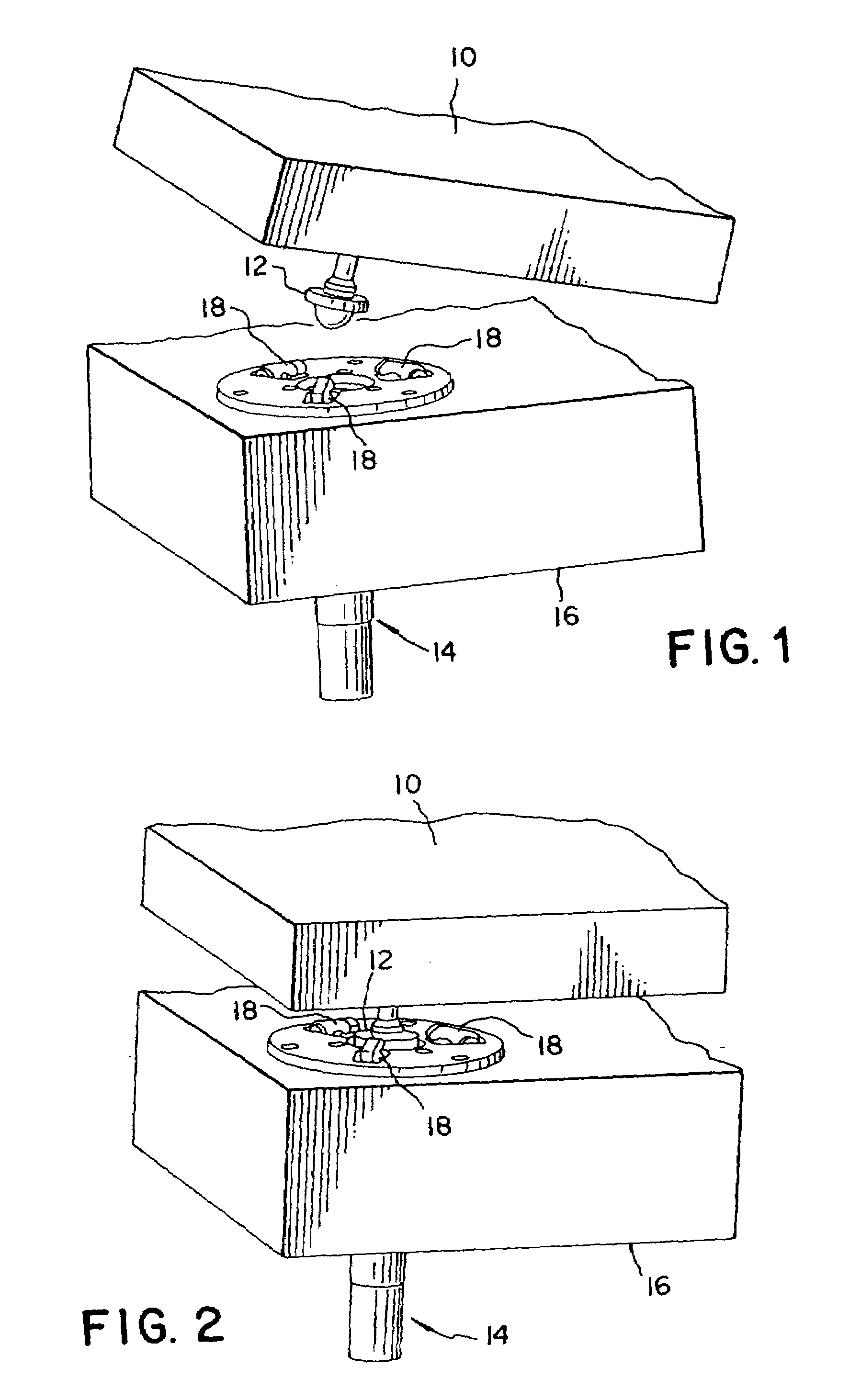
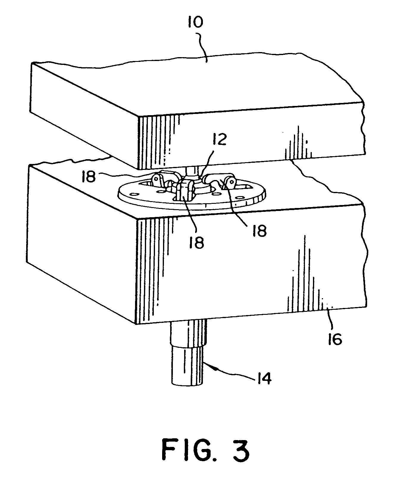
[0019]The present invention provides a nearly perfect kinematic mount between structural or optical elements and can easily be remotely controlled. Clamping force and drive position feedback can be incorporated to allow controlled closure and continuous force monitoring during and after clamping. A minimum number of moving parts maintains reliability at a value of 0.9994 or better. When in the closed position, the interface consists of a ball captured between two conical surfaces. A novel flexured ball and floating clamp plate is attached to the structure being deployed. The latch base is equipped with a conical seat to accept the ball, and three clamp fingers grip the floating clamp plate once the ball is seated in the socket. A lead screw driven axial cam serves to drive the clamping mechanism into both a clamped and a retracted position. A four bar linkage is formed by the latch cam, coupler link, follower link, and seat. Once the follower link is grounded on the seat, the couple...


PUM


Abstract

A reusable self-aligning precision latch, including a latch body for mounting a latch assembly, and an interface cone. A lead screw, coupled to the latch body on one end, pivots at an interface on the latch body allowing for self-alignment. A drive cam having a plurality of surfaces and positioned on the lead screw engages a plurality of linkage assemblies such that at least two links are driven. A flexure ball assembly clamped by the plurality of linkage assemblies to the latch body with a pivoting clamp plate such that all clamping forces between the pivoting clamp plate and the latch body are equalized. A motor for closing and opening the self-aligning precision latch by turning the lead screw to apply and release, respectively, the clamping forces between the pivoting clamp plate and the latch body.

Description

FIELD OF THE INVENTION[0001]This invention relates generally to actuated mechanical interlock mechanisms and, more particularly, to high reliability, high stability latching of deployable optical metering structures.BACKGROUND OF THE INVENTION[0002]To extend the range of astronomical telescopes, it is necessary to increase the effective aperture. This implies that larger diameter primary mirrors must be employed. The current state of the art has reached the practical size limit of monolithic mirrors. As a result, segmented primary mirrors that include multiple mirrored petals around a monolithic mirrored center segment have been devised. A space borne telescope employing segmented primary mirrors will require deployment once in orbit. Linear, stable, high stiffness precision latches, with high reliability values, should be used to interlock the metering structure, once the mirror is deployed, to maintain mirror performance. The probability of latch failure during system deployment h...

Claims


Application Information

Patent Timeline
Patent Type & Authority Patents(United States)
IPC IPC(8): G02B7/182G02B7/183
CPCG02B7/183Y10T403/599Y10T403/597Y10T403/608Y10T403/591Y10T403/602
Inventor O'BRIEN, MICHAEL J.COLLELUORI, RICHARD A.
Owner EXCELIS INC
Why Eureka
Try Eureka