Replenishing developer and developing method

a developer and developing method technology, applied in the field of revlenishing developer and developing method, can solve the problems of large stress on the carrier of the developer vessel, accelerated image deterioration, and change in image density or fog, and achieve the effect of stable image formation and stable image formation

Inactive Publication Date: 2005-08-30
CANON KK
View PDF27 Cites 31 Cited by
  • Summary
  • Abstract
  • Description
  • Claims
  • Application Information

AI Technical Summary

Benefits of technology

[0017]A more specific object of the present invention is to provide a replenishing developer allowing stable image formation over a life of a developing apparatus or an image forming apparatus including the developing apparatus.
[0018]A further object of the present invention is to provide a replenishing developer containing a wax-containing toner liable to cause carrier deterioration but still allowing stable image formation over a long period.

Problems solved by technology

As a result, the carrier is liable to be soiled with toner components transferred to the carrier or to receive a stress in the developer vessel, so that the resin coating layer thereof is peeled off to affect the developer performances, such as the chargeability, thus resulting in a change in image density or occurrence of fog.
However, the carrier used therein is an iron powder carrier having a large saturation magnetization, so that the carrier in the developer vessel receives a large stress and is liable to be deteriorated on repetition of image forming cycles.
As a result, the image deterioration is liable to be accelerated unless the replenishing carrier amount is increased.
However, according to these methods, the amount of exchanged carrier varies depending on the change in toner consumption amount, so that the resistivity or chargeability of the developer in the developer vessel is changed, thus being liable to cause a change in image density.
As an actual measure, however, it is very difficult to sequentially replenish plural types of toners containing carriers of different properties to a single developer vessel so as to to be free from mutual mixing because of a remarkable difference in specific gravity between the carrier and the toner.
Moreover, as a carrier is blended with a larger amount of toner, the carrier is liable to be deteriorated, so that it is difficult to obtain stable images for a long period.
Accordingly, in the case of using a developer containing a carrier having a large true specific gravity for a long period, there are liable to be encountered difficulties of (a) toner filming, (b) carrier breakage and (c) toner deterioration, thus resulting in developer deterioration and accompanying image quality deterioration of developed images.
The above difficulties (a)-(c) are also liable to be caused in the case of a large carrier particle size also exerting a large load on the developer, whereby the developer is liable to be deteriorated.
In this case, the developer is liable to have (d) an inferior thin-line reproducibility.
On the other hand, if the carrier particle size is decreased, (e) carrier attachment onto an electrostatic image-bearing member is liable to occur.
Further, in case where the toner particle size is retained at constant and the carrier particle size alone is decreased, (f) the toner is liable to have a broader charge distribution, so that an excessively charged portion of toner is liable to be attached even at non-image part on the image-bearing member to result in “fog” of images particularly in a low-humidity environment.
Unless a large amount of magnetic material is contained, however, the magnetic fine particle-dispersed resin carrier is liable to have (g) a low saturation magnetization relative to its particle size, so that the carrier attachment onto the electrostatic image-bearing member is liable to occur.
Further, a magnetic fine particle dispersion-type resin carrier containing a large amount of magnetic material is liable to have a weaker impact resistance due to an increased amount of magnetic material relative to the binder resin, the carrier is liable to cause drop-off or isolation of the magnetic material therefrom at the time of forming a developer layer in a prescribed thickness on the developing sleeve by means of a developer layer thickness regulating member, so that the developer is liable to be deteriorated.
Particularly, a magnetic fine particle-dispersed resin carrier containing a large amount of magnetite having, low resistivity, is liable to have a low resistivity, so that (h) image failure is liable to occur due to leakage of a developing bias voltage, and difficulties, such as developer conveyance failure or insufficient mixing with the toner is liable to occur due to a high residual magnetization.
However, the resin-coated carrier is liable to cause an excessive charge (so-called charge-up) of the toner in the case of a high carrier resistivity due to an increase in coating resin amount.
Further, in the case of a small coating resin amount, the carrier is caused to have too low a resistivity, thus being liable to result in image failure due to leakage of developing bias voltage.
Further, depending on a certain coating resin, even when exhibiting a measured resistivity value which is generally regarded as an appropriate value, such a resin-coated carrier is liable to cause image failure due to leakage of developing bias voltage or excessive charge of the toner in a low-humidity environment.

Method used


Image

  • Replenishing developer and developing method
  • Replenishing developer and developing method
  • Replenishing developer and developing method

Examples


examples

[0251]Hereinbelow, the present invention will be described more specifically based on Examples, which however should not be construed to restrict the scope of the present invention.

Production of Toners

[0252]Into 710 wt. parts of deionized water, 450 wt. parts of 0.1 mol / l-Na3PO4 aqueous solution was added, and after being heated to 60° C., the system was stirred at 13000 rpm by a high-speed stirrer (“TK-Homomixer”, made by Tokushu Kika Kogyo K.K.). Then, 68 wt. parts of 1ml / 1-CaCl2 aqueous solution was gradually added thereto to form an aqueous medium of pH 6 containing calcium phosphate.

[0253]On the other hand, the following ingredients:

[0254]

Styrene166wt. partsn-Butyl acrylate34wt. partsCopper phthalocyanine pigment10wt. partsDi-t-butylsalicylic acid Al compound1.5wt. partsAmorphous polyester10wt. partsMonoester wax20wt. parts(Mw = 500, Mn = 400, Mw / Mn = 1.25)

were sufficiently dispersed by means of a media dispersing machine at room temperature. After being separated from the dis...

example a-1

[0292]The above-prepared Magnetic carrier A-1 in 92 wt. parts and Cyan toner A-1 in 8 wt. parts were blended in a V-shaped blender to prepare Starting Cyan developer A-1.

[0293]On the other hand, Magnetic carrier A-1 and Cyan toner A-1 were blended in a weight ratio of 1:19 to provide Replenishing Cyan developer A-1.

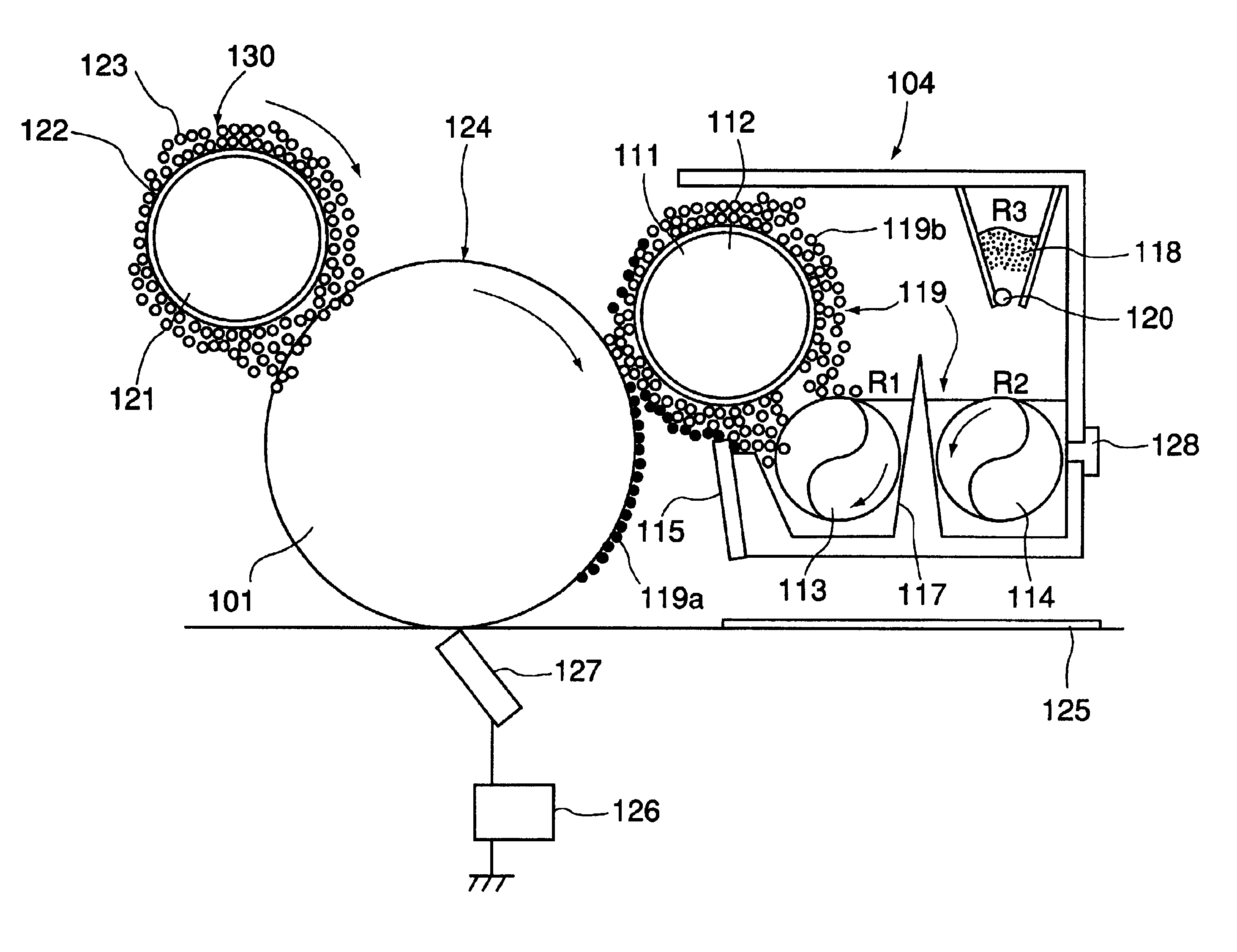
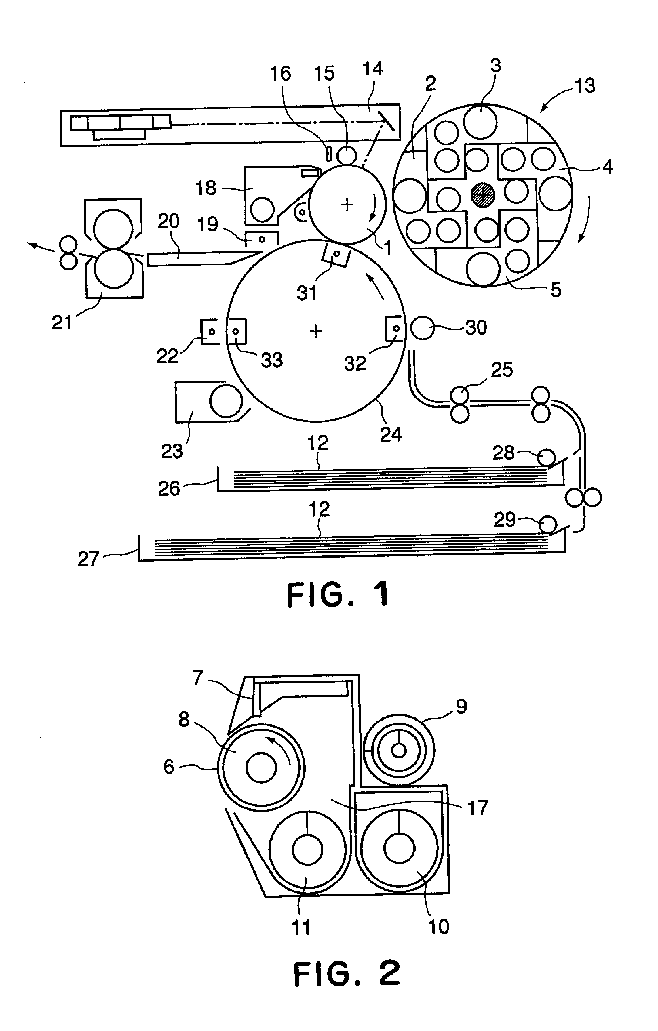
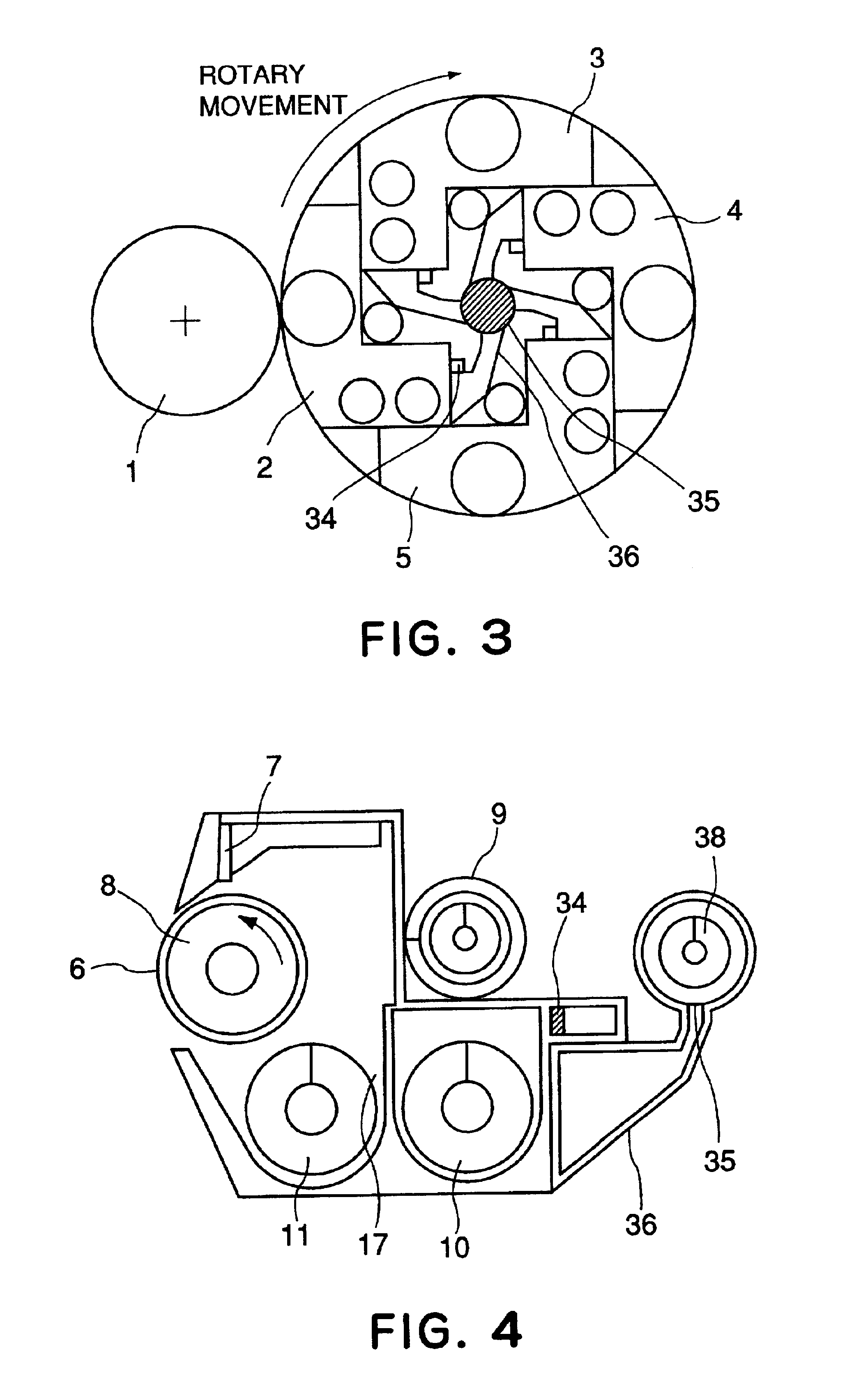
[0294]A commercially available copying machine (“GP55”, made by Canon K.K.) was re-modeled as follows to provide a test copying machine. More specifically, the developing apparatus was re-modeled into a form described with reference to FIGS. 3 and 4 including a developing sleeve having a surface roughness Rz=12.1 μm formed by sand-blasting a 16 mm-dia. SUS sleeve.

[0295]The charging member was re-modeled into a magnetic brush charger (130) as illustrated in FIG. 5 comprising Charger magnetic particles a (123) prepared above so that the magnetic brush charge was rotated at a speed of 100% relative to that of and in a direction opposite to the photosensitive member at an abu...

example a-2

[0322]The preparation of developers and evaluation were performed in the same manner as in Example 1 except for using Cyan toner A-6 instead of Cyan toner A-1.

[0323]As shown in Table 1, image forming performances were somewhat lowered with a practically acceptable degree in the H / H environment. This may be attributable to a lowering in transferability due to somewhat lower sphericity of the toner.


PUM


Abstract

An electrostatic latent image on an image-bearing member is developed with a two-component developer comprising a toner and a carrier stored in a developer vessel while supplying as required a replenishing developer to the developer vessel. The replenishing developer comprises 1 wt. part of a carrier and 2-50 wt. parts of a toner, wherein the carrier is a magnetic fine particle-dispersed resin carrier comprising at least inorganic compound particles and a carrier binder resin, and the toner has a weight-average particle size of 3 to 10 μm and contains 1 to 40 wt. % of solid wax.

Description

FIELD OF THE INVENTION AND RELATED ART[0001]The present invention relates to a developer for replenishment used in electrophotography, electrostatic recording, etc., and a developing method using the developer.[0002]In the developing method practiced at present using a two component-type developer comprising a toner and a carrier, the toner is consumed during the development, and the carrier is not consumed but is caused to remain in a developer vessel. As a result, the carrier is liable to be soiled with toner components transferred to the carrier or to receive a stress in the developer vessel, so that the resin coating layer thereof is peeled off to affect the developer performances, such as the chargeability, thus resulting in a change in image density or occurrence of fog.[0003]In order to solve the problem, Japanese Examined Patent Publication (JP-B) 5-21591 has disclosed a developing apparatus (a so-called “trickle developing apparatus”) wherein a carrier is supplied together ...

Claims


Application Information

Patent Timeline
Patent Type & Authority Patents(United States)
IPC IPC(8): G03G9/087G03G9/10G03G9/107G03G9/113G03G9/08
CPCG03G9/08782G03G9/10G03G9/107G03G9/1136G03G9/10884G03G9/1087G03G9/1075G03G9/10882G03G9/108G03G9/1085G03G9/08
Inventor OKADO, KENJIMIKURIYA, YUSHIYOSHIZAKI, KAZUMIIKEDA, NAOTAKA
Owner CANON KK
Why Eureka
Try Eureka