Superconducting cable termination

a superconducting cable and termination technology, applied in the direction of superconducting magnets/coils, magnetic bodies, connection contact material materials, etc., can solve the problems of high stress, poor dielectric properties in the warm gaseous state, and complex terminations, etc., to achieve the effect of reducing radial heat leakage to the environment, increasing capacity, and high current density of hts conductors

Inactive Publication Date: 2005-08-30
SOUTHWIRE CO LLC
View PDF12 Cites 20 Cited by
  • Summary
  • Abstract
  • Description
  • Claims
  • Application Information

AI Technical Summary

Benefits of technology

[0015]The termination consists of the normal electrically insulated conductors contained in a thermally insulated conduit. The termination conduit consists of three distinct regions. A cold end housing for making connections between the normal conductors and the superconductors. An ambient temperature housing for making connections between the normal conductors and the internal connection of the ambient temperature hermetic bushing. A transition duct connects the cold housing and the ambient housing through which the normal conductors and insulators pass. The transition duct is sized so that the insulators and conductors completely fill the duct. Sealant compounds, elastomer seals, and mechanical seals close the gaps between the insulators, conductors, and transition duct. One or more capillary passages through, or parallel to, the termination duct connects the cold housing end to the ambient housing end to maintain pressure equilibrium across the termination duct, thereby limiting liquid coolant from flowing from the cold housing to the warm housing. The conductors and transition duct are of a size and length so as to minimize the heat flow through the normal conductors from the ambient temperature housing to the cold housing.
[0019]Thus, the termination allows for a natural temperature gradient in the copper pipe conductors inside the termination which enables the controlled flashing of the coolant, i.e. pressurized liquid nitrogen to gaseous nitrogen. Thus the entire termination is near the nitrogen supply pressure thereby eliminating the high voltage and shield cold bushings, a highly stressed component used in prior art HTS cables.
[0021]Other aspects of the design include: (1) a sliding seal to allow for cable contraction as it is cooled from room temperature to ˜72-82 K and (2) specialized seals and static vacuum with multi-layer superinsulation to minimize radial heat leak to the environment.

Problems solved by technology

Various types of terminations have been used in the prior art, but these terminations are complex, subject to stress and susceptible to failure.
The cold bushing in such designs is a highly stressed component and prone to failure.
This is done because the coolant, helium, has poor dielectric properties in the warm gaseous state.

Method used


Image

  • Superconducting cable termination
  • Superconducting cable termination
  • Superconducting cable termination

Examples


Embodiment Construction

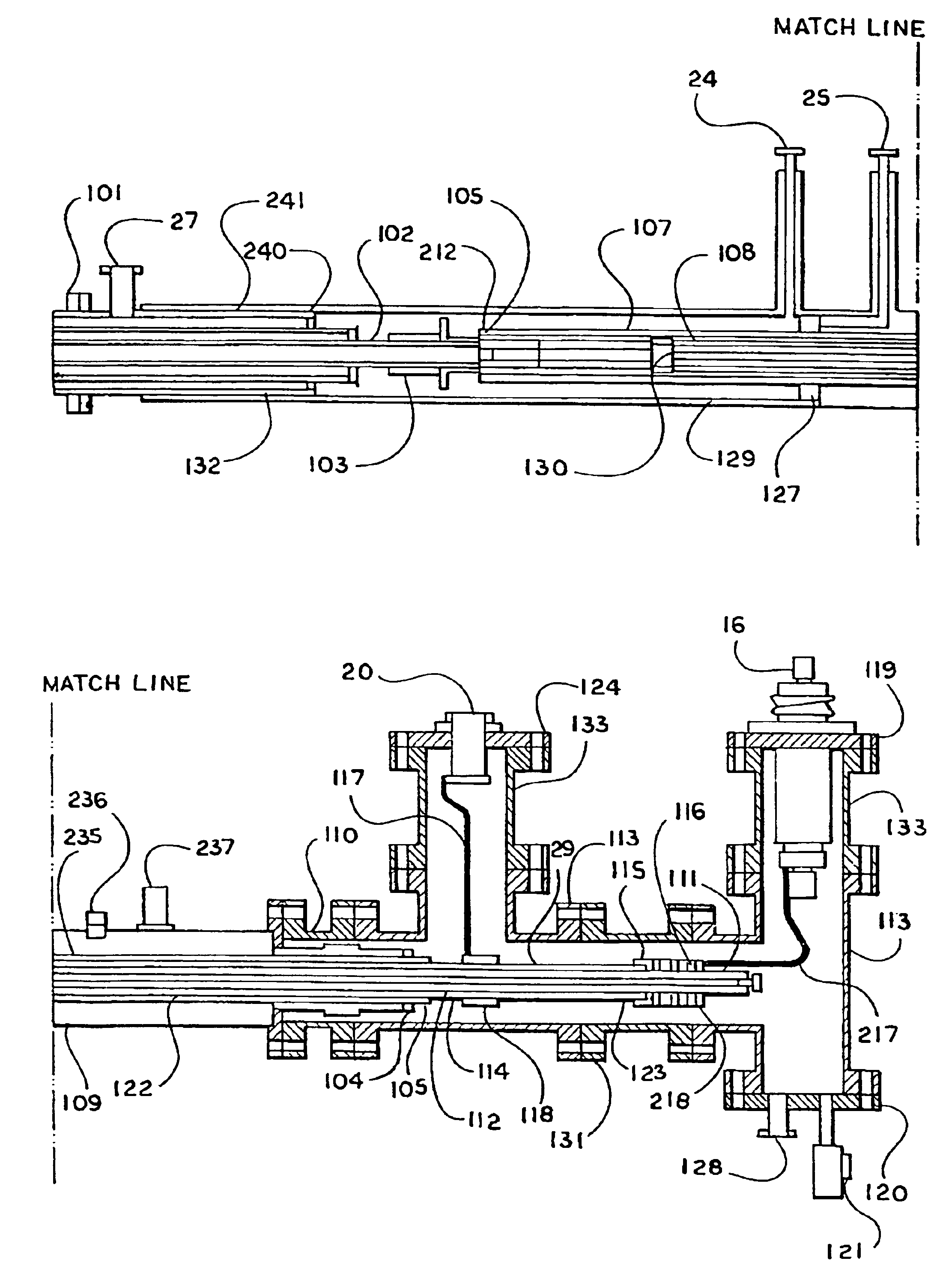
[0036]While the exact design of the superconducting cable may vary, the embodiment of this invention described and illustrated here is for connecting a coaxial superconducting cable consisting of a superconducting center phase conductor and an outer superconducting shield conductor, to a pair of copper conductors that make utilization of the cable for electrical power transmission possible. The present embodiment is designed for continuous 1.25 kA operation at 7.2 kVAC operation and 110 kV BIL and has been operated continuously at 13 kVAC and withstood 120 kV impulse. The same principles can be used to design superconducting terminations and splices that have multiple phase conductors operate at different current and voltage levels.

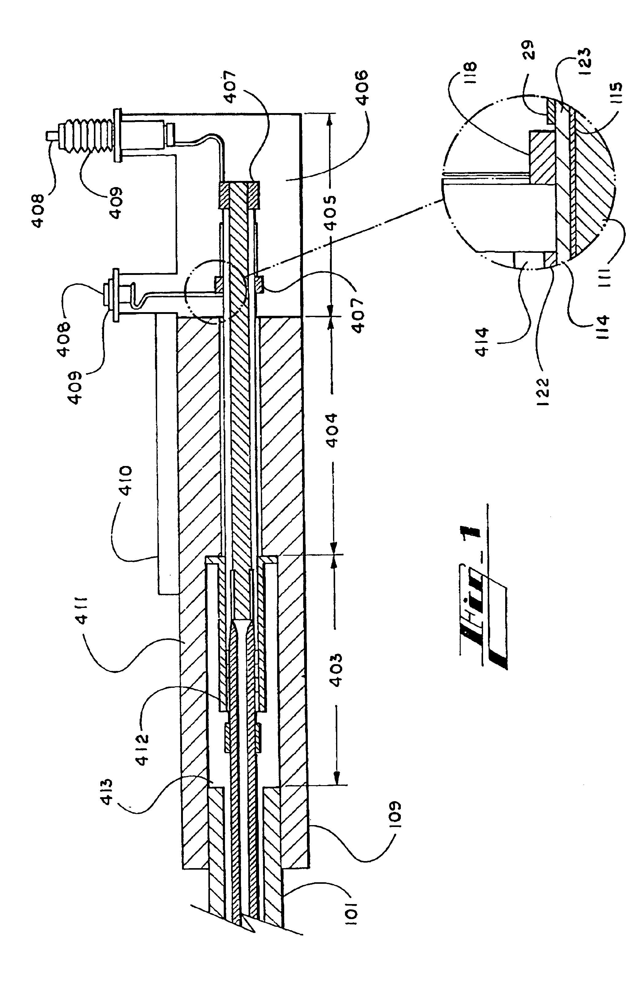
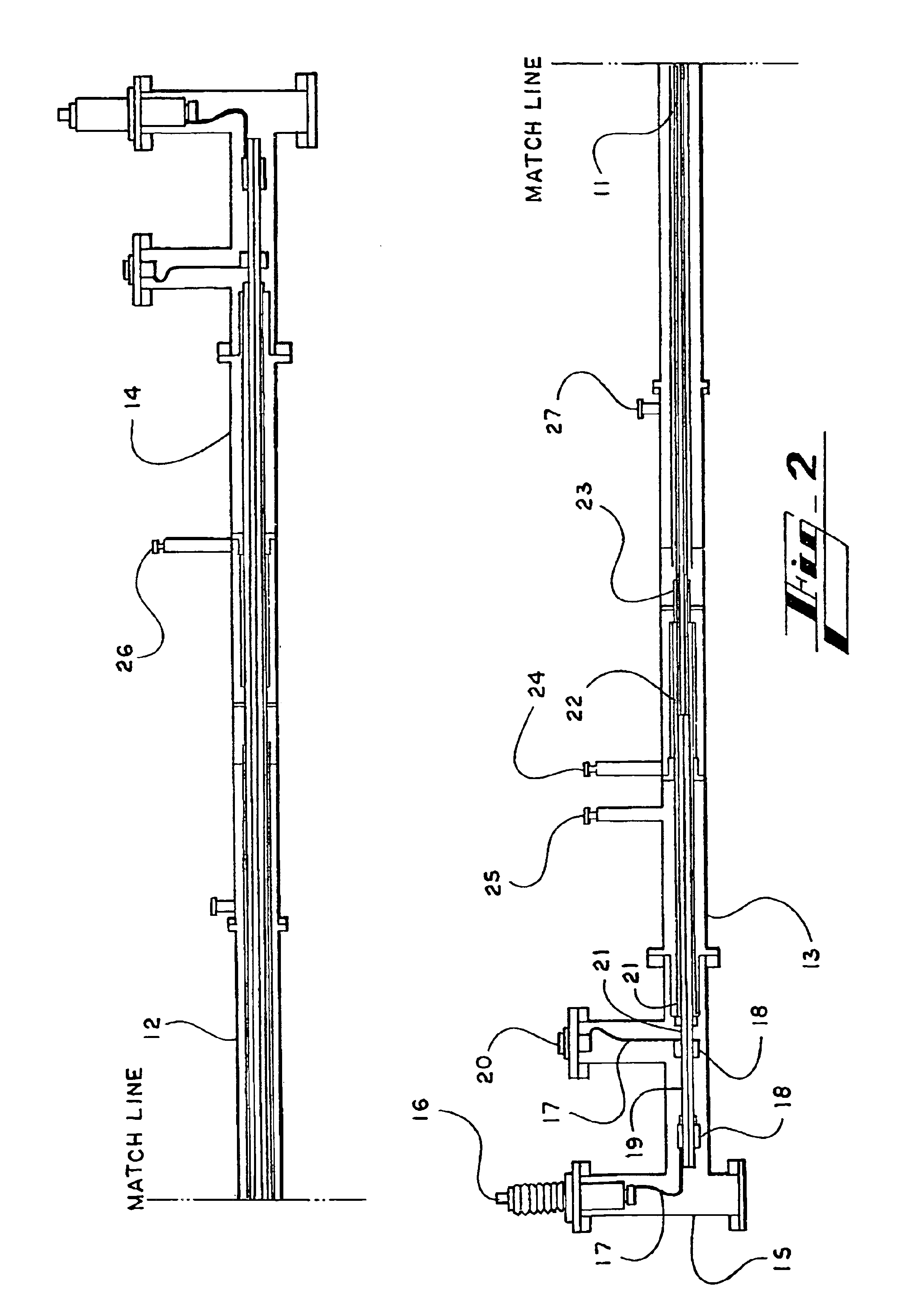
[0037]FIG. 1 shows a schematic representation of the superconducting cable termination of the present invention. Referring to FIG. 1, superconducting cable 101 is shown in the conduit which is surrounded by termination conduit 109. Cold section 403 in ter...


PUM

PropertyMeasurementUnit
temperatureaaaaaaaaaa
lengthaaaaaaaaaa
lengthaaaaaaaaaa

Abstract

Disclosed is a termination that connects high temperature superconducting (HTS) cable immersed in pressurized liquid nitrogen to high voltage and neutral (shield) external bushings at ambient temperature and pressure. The termination consists of a splice between the HTS power (inner) and shield (outer) conductors and concentric copper pipes which are the conductors in the termination. There is also a transition from the dielectric tape insulator used in the HTS cable to the insulators used between and around the copper pipe conductors in the termination. At the warm end of the termination the copper pipes are connected via copper braided straps to the conventional warm external bushings which have low thermal stresses. This termination allows for a natural temperature gradient in the copper pipe conductors inside the termination which enables the controlled flashing of the pressurized liquid coolant (nitrogen) to the gaseous state. Thus the entire termination is near the coolant supply pressure and the high voltage and shield cold bushings, a highly stressed component used in most HTS cables, are eliminated. A sliding seal allows for cable contraction as it is cooled from room temperature to ˜72-82 K. Seals, static vacuum, and multi-layer superinsulation minimize radial heat leak to the environment.

Description

CROSS-REFERENCE TO RELATED APPLICATION[0001]This application claims the benefit of priority of U.S. Provisional Application No. 60 / 329,234, filed Oct. 12, 2001.BACKGROUND OF THE INVENTION[0002]The present invention relates to a termination for connecting superconducting and high temperature superconducting (HTS) cables operating at sub-ambient temperatures to cables operating at ambient temperature.[0003]It is known that superconductors are metals, alloys, or oxides thereof, and in general are compounds having practically zero resistivity below a transition temperature, i.e. the critical temperature. A superconducting cable must be operated below its critical temperature, therefore it is cooled during use by, for example, cryogenic cooling fluids. Metal and alloy superconductors have critical temperatures below 20° K while metal oxide (ceramic) superconductors have higher critical temperatures on the order of 80° K thus distinguishing them from the former materials and separating th...

Claims


Application Information

Patent Timeline
Patent Type & Authority Patents(United States)
IPC IPC(8): H01F6/06H02G15/00H02G15/34
CPCH01F6/065H02G15/34Y02E40/648Y02E40/60
Inventor SINHA, UDAY K.TOLBERT, JERRY
Owner SOUTHWIRE CO LLC
Why Eureka
Try Eureka