Method and apparatus for a quadrupole transmitter for directionally sensitive induction tool

a directionally sensitive induction and quadrupole transmitter technology, applied in the direction of instruments, scientific instruments, measurement devices, etc., can solve the problems of inability to distinguish whether a layer is above or below the borehole, and the conductivity of the induction voltage measurement to be in error, so as to reduce the eddy current

Inactive Publication Date: 2005-08-30
BAKER HUGHES INC
View PDF3 Cites 21 Cited by
  • Summary
  • Abstract
  • Description
  • Claims
  • Application Information

AI Technical Summary

Benefits of technology

[0015]The new quadrupole system of the present invention in combination with MPR enables MWD resistivity measurements with azimuthally sensitivity. The system consists of a dual loop transmitter and one coil receiver placed between transmitting coils. The moments of the transmitting and receiving coils are substantially perpendicular to the borehole axis. The optimal length of the system is (about ) 1 m. In order to provide large depth of investigation the quadrupole system is preferably combined with existing MPR tools. The present invention provides a quadrupole system with azimuthal resolution in the directional mode and a MPR high depth of investigation in the deep resolution mode. To reduce ambiguity due to zero crossings in the data multi-frequency measurements as well as the measurements of both in-phase and quadrature components are performed.
[0017]Preferably, both directional and deep measurement modes are combined in one single tool. The tool comprises at least two transmitter coils (a quadruple transmitter) and an array of transversal coils in the receiver portion of the tool. The moments of the transmitting and receiving coils are perpendicular to the borehole axis. The transmitter provides a switch to switch polarity of the current in each of the transmitter coils. Several receiving coils are placed at the different distances from the quadruple transmitter, for example 1 meter between receiving coils. The present invention provides a resistivity tool that acquires data at several operating frequencies in the range of 100 kHz to 2 MHz. The preferred tool provides a controller and control program that performs switching polarity of the current in the transmitter coils so that the data of both directional and deep mode can be acquired. The deep mode data are acquired when magnetic moments of two transmitting loops are switched so that the moments point in the same direction and the directional mode data are acquired when the moments point in opposite directions. The opposing moments in the directional mode also reduce eddy currents induced in the conductive drill or tool.

Problems solved by technology

If the layers are not perpendicular to the axis of the instrument, the conductivity of the media surrounding the instrument can vary azimuthally, causing the inferences about the conductivity from the measurements of the induction voltage to be in error.
A limitation to the electromagnetic induction resistivity well logging instruments known in the art is that they typically include transmitter coils and receiver coils wound so that the magnetic moments of these coils are substantially parallel only to the axis of the instrument.
It is not possible to distinguish whether a layer is above or below the borehole from these data alone.

Method used


Image

  • Method and apparatus for a quadrupole transmitter for directionally sensitive induction tool
  • Method and apparatus for a quadrupole transmitter for directionally sensitive induction tool
  • Method and apparatus for a quadrupole transmitter for directionally sensitive induction tool

Examples


Embodiment Construction

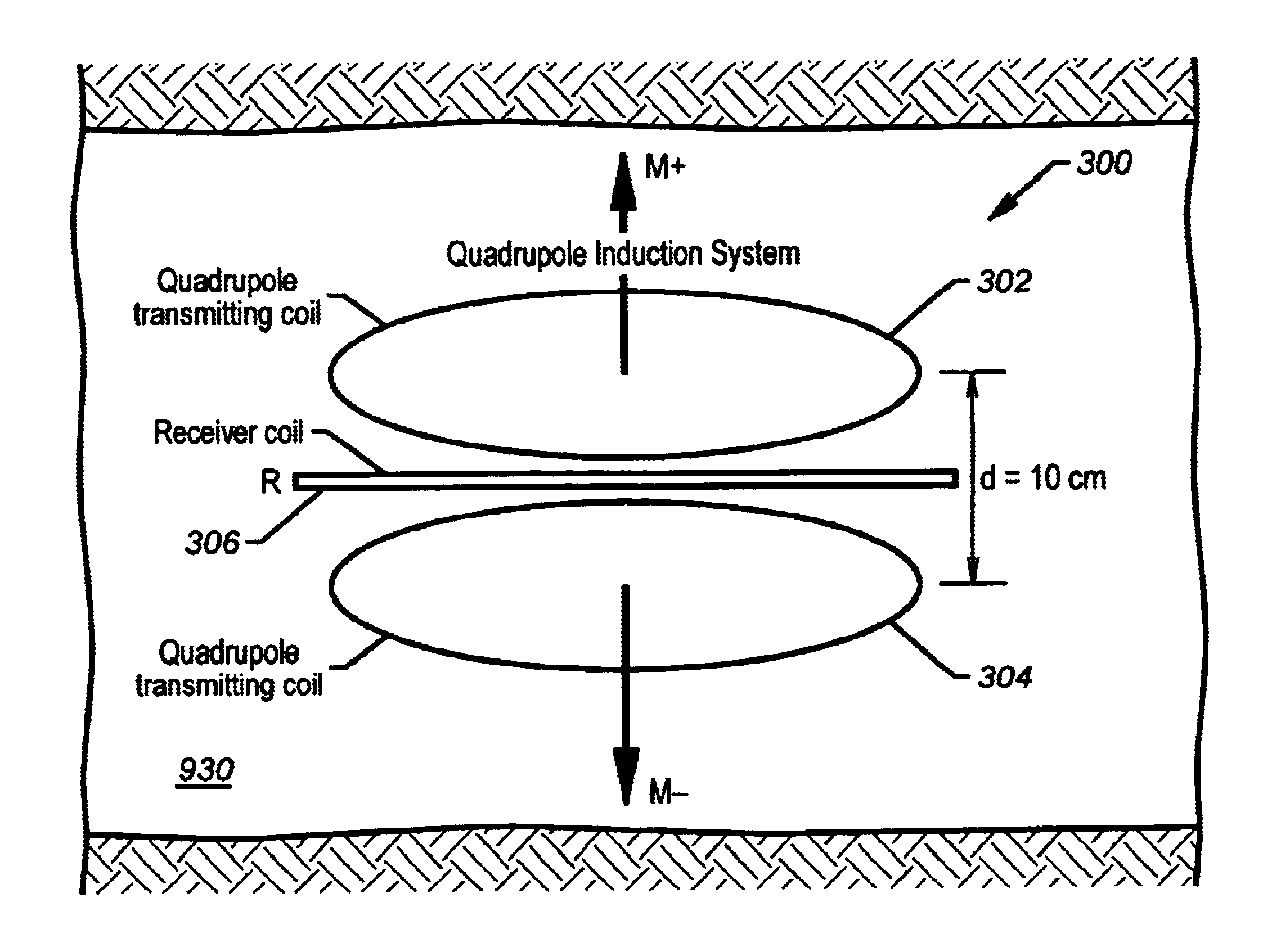
[0033]The present invention provides a method and apparatus for performing resistivity measurements with azimuthal resolution. The present invention provides for larger depth of investigation for resistivity (Rt) determination and bed boundary detection during reservoir navigation along with enhanced accuracy over a broad range of resistivities. The present invention provides MPR with resolving capability in azimuthal direction that leads to a increased and more effective usage of MPR for geo-steering.

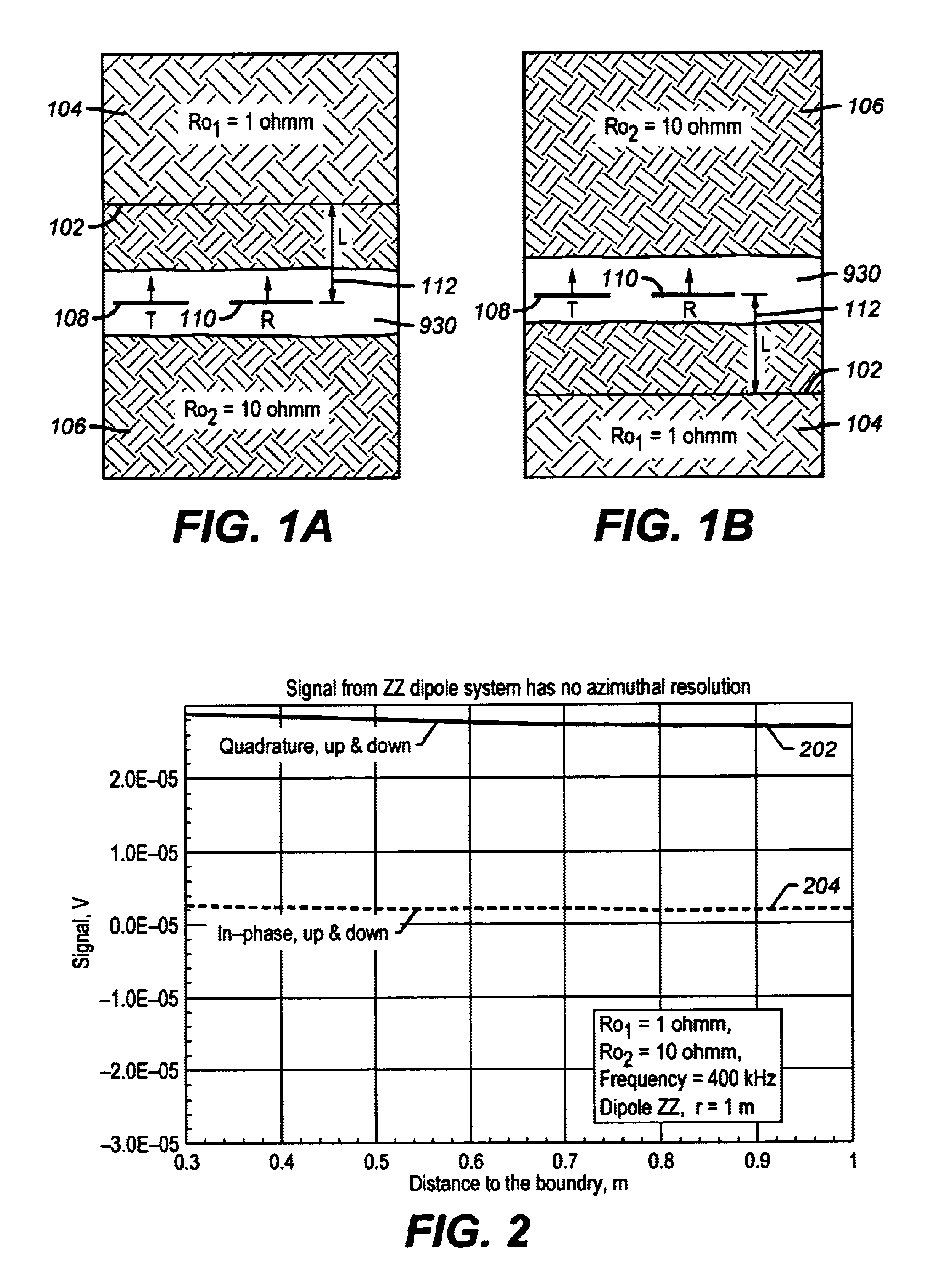
[0034]Turning now to FIG. 1, FIG. 1 illustrates a two-layered formation models with up / down boundary 102. Resistivities of the layers 106, 104, are ρ1=10 ohm-m and ρ2=1 ohm-m respectively. The excitation dipole 108 is oriented in the same direction as receiving dipole 110. The tool (not shown) is placed at a different distance L, containing dipoles 108, 110 from the boundary 102 inside the resistive layer. The tool traverses a bore hole 930 considered to be horizontal and parallel to l...


PUM


Abstract

The present invention provides a method and apparatus for performing resistivity measurements for the purpose of geo-steering with 180-degree azimuth resolution. All the measurements represent a complementary set of data acquired in two operational modes. The directional mode providing sensitivity of the received signals to the azimuth characteristics of the formation. The deep mode provides a large depth of investigation for resistivity determination and bed boundary detection. The directional mode can be implemented using one receiving coil placed in between quadruple type transmitter. The deep mode represents either array induction measurements or multiple propagation resisitivity (MPR) measurements that provide high depth of investigation for resistivity determination and bed boundary detection.

Description

CROSS REFERENCE TO RELATED APPLICATIONS[0001]The patent application claims priority from and is a continuation of U.S. patent application Ser. No. 10 / 388,871 filed on Mar. 14, 2003 entitled “A Method and Apparatus for a Quadrupole Transmitter for Directionally Sensitive Induction Tool” by G. Itskovich, A. Bespalov and B. Chakarov which claims the benefit of Provisional application No. 60 / 408,615, filed Sep. 6, 2002.BACKGROUND OF THE INVENTION[0002]1. Field of the Invention[0003]The present invention pertains to the field of performing resistivity measurements for the purpose of geo-steering in two operational modes. A directional mode provides sensitivity of the received signals to the azimuthal characteristics of the formation and a deep mode provides large depth of investigation for resistivity determination and bed boundary detection relative to the borehole and tool.[0004]2. Summary of the Related Art[0005]Electromagnetic induction and wave propagation logging tools are commonly...

Claims


Application Information

Patent Timeline
Patent Type & Authority Patents(United States)
IPC IPC(8): G01V3/28G01V3/18
CPCG01V3/28G01V3/30
Inventor ITSKOVICH, GREGORYBESPALOV, ALEXANDERTCHAKAROV, BORISLAV J.
Owner BAKER HUGHES INC
Why Eureka
Try Eureka