System and method for dead-band determination for rotational frequency detectors

a detector and rotational frequency technology, applied in pulse automatic control, pulse technique, instruments, etc., can solve the problems of circuit drifting out of phase lock, circuit losing lock, and pll temporarily losing lock

Inactive Publication Date: 2005-08-30
AVAGO TECH INT SALES PTE LTD
View PDF3 Cites 6 Cited by
  • Summary
  • Abstract
  • Description
  • Claims
  • Application Information

AI Technical Summary

Benefits of technology

[0010]In one embodiment a system and method is arranged for bridging the dead-band when asynchronous signals are compared against each other. There is developed a pair of phase related signals from one of the signals, each phase related signal phase shifted from each other, but having the same frequency as the signal from which it was derived. The other frequency signal is compared against each

Problems solved by technology

When the circuit is operating in or near phase lock, any glitch or false indication from the frequency detector dead-band indicator could cause the PLL to lose lock.
Current dead-band detectors produce glitches due to metastability, which then causes the PLL to temporarily lose lock.
If the dead-band circuit gives a false indication or produces a

Method used


Image

  • System and method for dead-band determination for rotational frequency detectors
  • System and method for dead-band determination for rotational frequency detectors
  • System and method for dead-band determination for rotational frequency detectors

Examples


Embodiment Construction

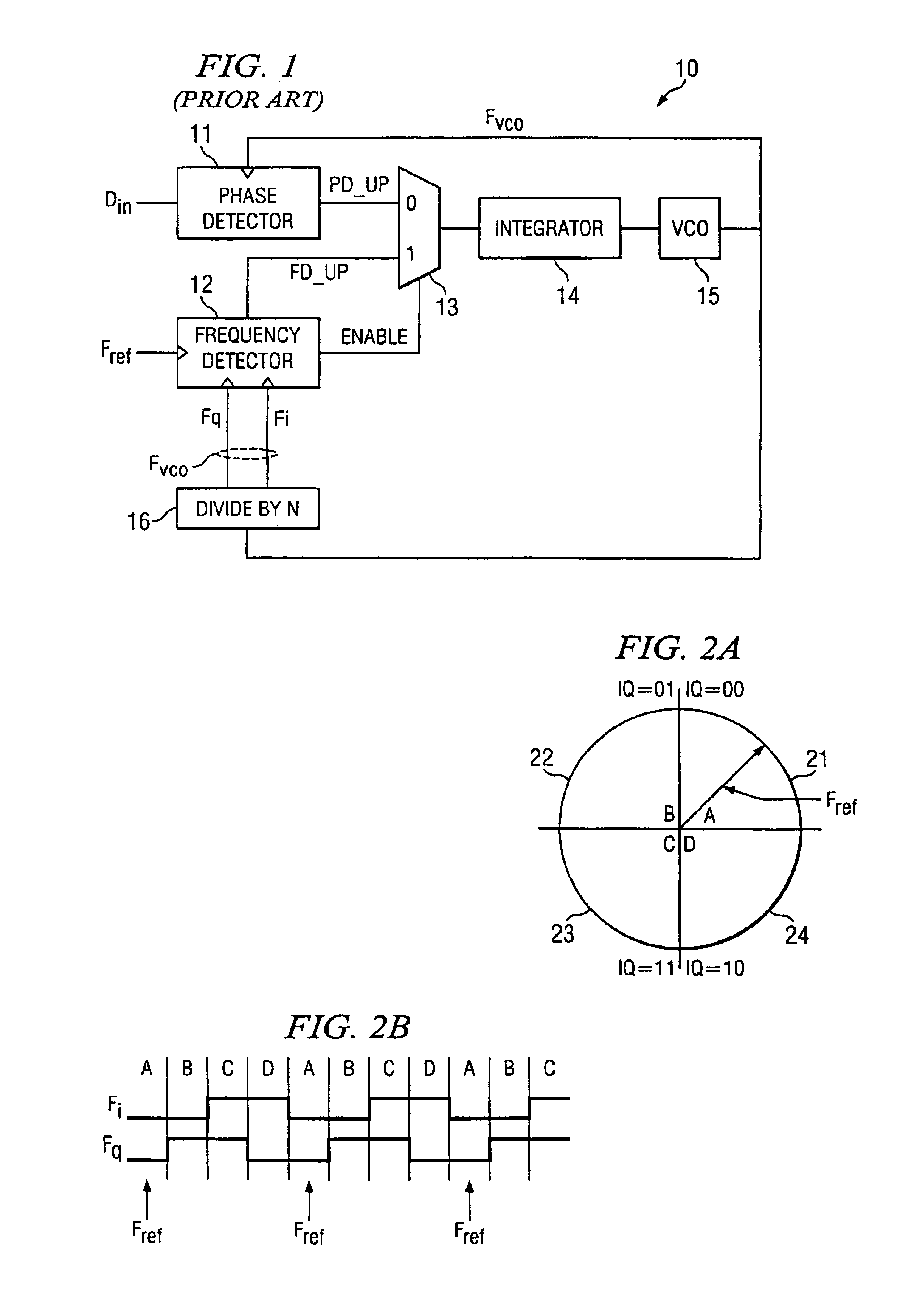
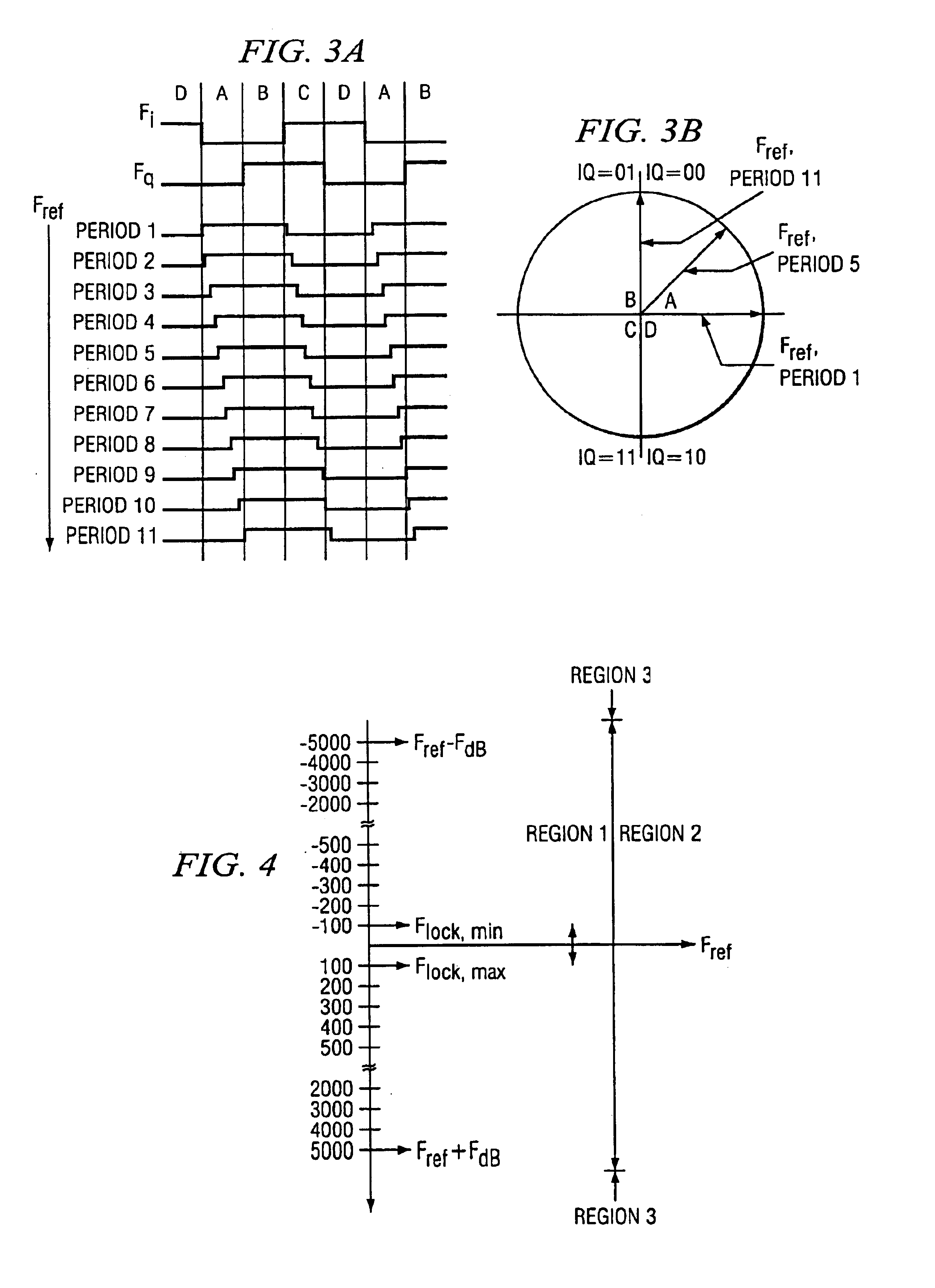
[0025]A digital implementation of rotational frequency detector 10 works by sampling two versions of an input clock, which are 90° out of phase (Fi and Fq), with a reference clock Fref. These signals can be thought of forming four quadrants labeled A, B, C, and D as shown in FIG. 2A. When the input frequency Fvco is identical to the reference frequency Fref, the phase of the reference clock is static with respect to the input frequency. The reference vector is also static and does not change quadrants. When the frequencies are different, the phase of the reference clock changes with respect to the input frequency and the reference vector can be thought of as rotating with respect to the input. The sign of the frequency difference can be found by the direction of rotation: either A,B,C,D, . . . or D,C,B,A, . . . . The magnitude of the frequency difference also has to be found and compared to the dead-band frequency.

[0026]As discussed above, circuit 10 is either under control of phase...


PUM


Abstract

In one embodiment a system and method is arranged for bridging the dead-band when asynchronous signals are compared against each other. There is developed a pair of phase related signals from one of the signals, each phase related signal phase shifted from each other, but having the same frequency as the signal from which it was derived. The other frequency signal is compared against each of the phase-related developed signals to generate an error signal which quadrature rotates when the first and second signals are out of frequency with each other. A control signal is generated when the quadrature rotation is outside a certain limit. The error signal is controllably buffered to insure that the error signal only occurs when the frequencies are offset for a selected period of time.

Description

TECHNICAL FIELD[0001]This invention relates to frequency synchronization circuits and more particularly to systems and methods for dead-band control for clock and data recovery circuits.BACKGROUND OF THE INVENTION[0002]Frequency detectors are used in a wide variety of circuits, such as, for example, phase locked loop (PLL) circuits in which the frequency range of the oscillator exceeds the pull-in range of the phase detector. The frequency detector must be able to 1) detect both the magnitude and polarity of the frequency difference, and 2) yield to the phase detector once the frequency error is determined to be within a small range (also referred to as the dead-band region). When the circuit is operating in or near phase lock, any glitch or false indication from the frequency detector dead-band indicator could cause the PLL to lose lock. Current dead-band detectors produce glitches due to metastability, which then causes the PLL to temporarily lose lock.[0003]A typical clock and da...

Claims


Application Information

Patent Timeline
IPC IPC(8): H03D13/00
CPCH03D13/003
Inventor GALLOWAY, BRIAN J.KNOTTS, THOMAS A.
Owner AVAGO TECH INT SALES PTE LTD
Why Eureka
Try Eureka