
Multi-station RF thermometer and alarm system

Inactive Publication Date: 2005-08-30
HEADWATERS RES & DEV
View PDF29 Cites 25 Cited by
  • Summary
  • Abstract
  • Description
  • Claims
  • Application Information

AI Technical Summary

Benefits of technology

[0010]It is another object of the present invention to disclose a multi-station RF thermometer and alarm system that provides accurate temperature or other weather parameter, such as humidity, sensing and transmission over wide temperature, humidity and distance ranges in a manner that requires low power consumption suitable for long-life battery operation.
[0014]Accordingly to one aspect of the present invention, the portable, battery-powered temperature station includes an analog temperature sensor providing a temperature signal representative of sensed temperature; an antenna; and a processor-controlled transmitter coupled to the antenna and to the temperature signal operative (1) to periodically convert the temperature signal to a digital representation of the sensed temperature, (2) to digitally encode a data frame having first information representative of the sensed temperature and second information representative of station ID, and (3) to transmit a predetermined integral number greater than one (1) of data frames each having said first and said second information at a random time. The randomized transmission times, and redundantly encoded temperature and transmitter ID data, cooperate to alleviate collision-induced contention and to provide reliable data transmission in noisy environments. In this embodiment, the temperature data is read every thirty (30) seconds and five (5) redundant data frames are randomly transmitted once every thirty (30) to sixty (60) seconds.
[0023]In further disclosed embodiments, each portable, battery-powered weather station is operative to alternatively transmit percent relative humidity and temperature data redundantly in accord with a schedule of transmission times unique to each portable, battery-powered weather station. The redundant transmission of weather data helps prevent noise interference at the multi-station base station, and the unique schedules of transmission times both held prevent contention-induced interference at the multi-station base station as well as allow the multi-station base station to enter battery-power-conserving mode when no receptions are scheduled from each of the portable weather stations.
[0025]A method of encoding data at the portable, battery-powered weather stations to maximize transmission range and detection sensitivity at the battery-powered multi-station base station is disclosed.

Problems solved by technology

This can be inconvenient, as this type of digital thermometer is not placed where it is most accessible and likely to be needed (e.g., next to a bed, on a desk, etc.), but where it must be placed to work.
Although in principle such transmitters may be remotely located to the base, environmental noise sources have generally limited their practical range and have given rise to erroneous telemetry and lack of operator confidence.
Not only has this resulted in increased overall costs, and undesirable multiplication of base stations, but the utility of such transmitter / base pairs has further been limited by contention-induced interference as transmissions from the multiple transmitters collide at each base station.
Moreover, both the hard-wired and RF temperature thermometers heretofore have had their utility limited by probe placement difficulties, whenever locations that are other than directly exposed and in the open are to be monitored, and by a general inability to provide information of comfort level or of weather situations that may endanger well-being.

Method used


Image

  • Multi-station RF thermometer and alarm system
  • Multi-station RF thermometer and alarm system
  • Multi-station RF thermometer and alarm system

Examples


Embodiment Construction

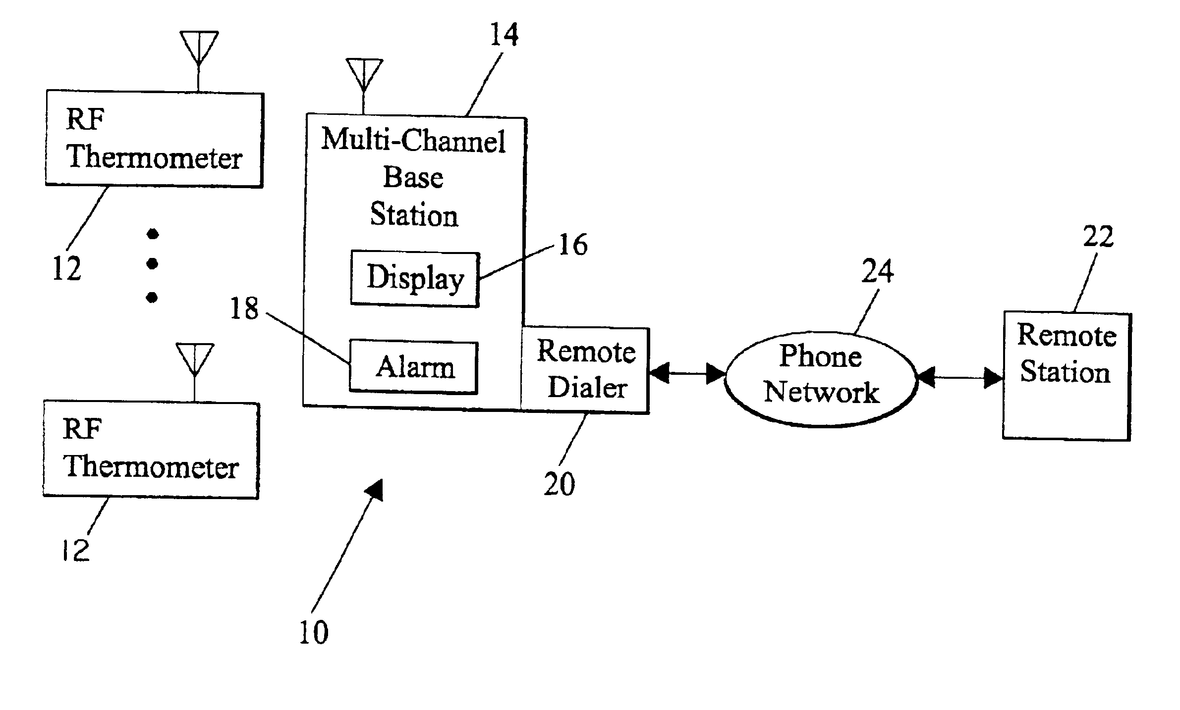
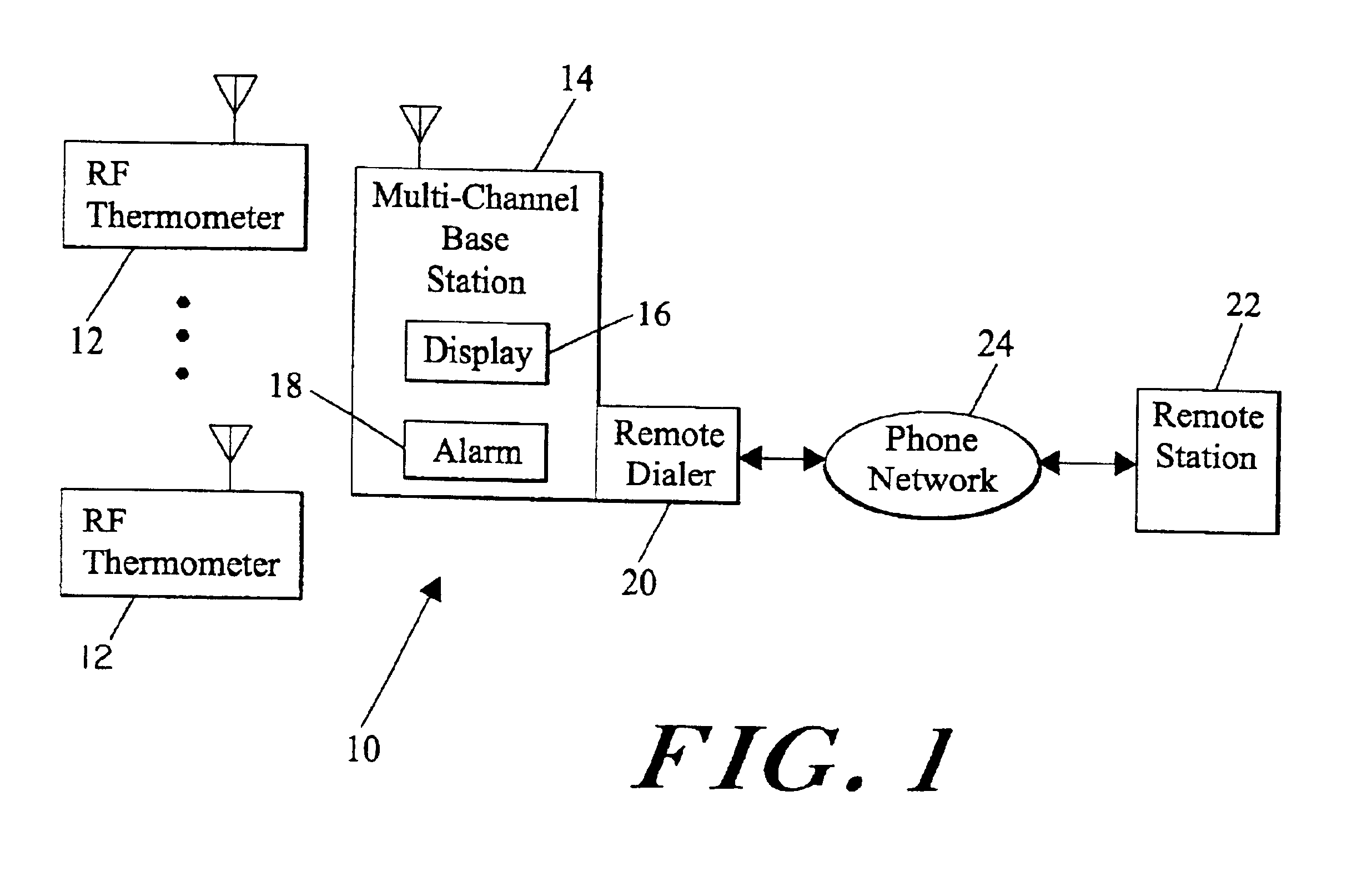
[0048]Referring now to FIG. 1, generally designated at 10 is a functional block diagram of the multi-station RF thermometer and alarm system in accord with the present invention. The system 10 includes a plurality of RF thermometers or other weather stations 12 to be described and a multichannel base station 14 in spaced apart relation to the plural RF thermometers 12. The system 10 is adapted for home, office and light industrial use. The RF thermometers 12 are portable, battery-powered devices that may be placed anywhere where temperatures are to be monitored. For example, one temperature transmitter 12 could be attached to the back of the house, another in the pool, a third in a green house, and a fourth in the garden, not shown.

[0049]The multi-channel base station 14 includes a receiver, not shown, to be described that receives the temperatures or other weather data transmitted by the plural RF thermometers 12 and displays temperature data received from the plural RF thermometer...


PUM


Abstract

A multi-station RF thermometer and alarm system measures temperatures and / or percent relative humidity at remote locations by RF weather stations, and displays received temperature and / or other weather data telemetry on a multi-station base station that provides out-of-bounds alarm signal indications whenever temperatures are outside of user-selectable minimum and maximum values. Randomized transmission times in one embodiment and two-phase unique transmission schedules in another lessen the possibility of on-going collisions between two or more transmitters contending for the base station at the same time. Redundant data transmission lessens the possibility of environmental noise interference. The redundant data, transmitted at random times in one embodiment, includes a unique channel ID code, house-keeping data, the current temperature and / or time-to-next-transmission data, and in another embodiment, transmitted at uniquely prescheduled times of two-phase transmission schedules, includes station location ID and transmission schedule phase. The weather parameter sensing transmitters operate at a low duty cycle with low peak current consumption resulting in long battery life. The multi-station base station may be AC- or battery-powered. Channel and station ID switches are provided on the remote temperature sensing transmitters and on the multi-station base station in one embodiment and a station ID number selection switch is provided in another transmitter embodiment.

Description

CROSS-REFERENCE TO RELATED APPLICATIONS[0001]This invention is a division of allowed continuation-in-part application Ser. No. 09 / 421,974 filed Oct. 20, 1999 now U.S. Pat. No. 6,300,871, which is a continuation of U.S. utility patent application Ser. No. 08 / 968,290 filed Nov. 12, 1997, now U.S. Pat. No. 6,046,674, each incorporated herein by reference.FIELD OF THE INVENTION[0002]This invention is drawn to the field of telemetry, and more particularly, to a novel multi-station RF thermometer and alarm system.BACKGROUND OF THE INVENTION[0003]Many of life's activities are heavily influenced by the temperature. Heretofore, hard-wired digital thermometers, such as the model IOTA1 and the model IOTA2 commercially available from TREND Industries, Inc., or the Electronic Weather Station With Alarm Clock, commercially available from CATHAY PACIFIC, measure temperature by a hard-wired probe, and display the measured temperature on an associated display. Such hard-wired digital thermometers, h...

Claims


Application Information

Patent Timeline
IPC IPC(8): G01K1/02G01K1/00
CPCG01K1/024
Inventor IRWIN, MICHAEL BRUCE CHRISTOPHER
Owner HEADWATERS RES & DEV
Learn More