Wavemeter having two interference elements

a technology of interference elements and wavemeters, applied in the field of wavemeters, can solve the problems of expensive and very precise measurement of wavemeters, and achieve the effect of improving the accuracy and accuracy of measurement results

Inactive Publication Date: 2005-08-30
AGILENT TECH INC
View PDF9 Cites 57 Cited by
  • Summary
  • Abstract
  • Description
  • Claims
  • Application Information

AI Technical Summary

Benefits of technology

[0020]It is preferred to use a respective “split” photodiode to detect the power of the resulting parts of the beam with a single but split photodiode. This brings the advantage that all parts of the photodiode have the same characteristic features.

Problems solved by technology

To adjust the wavelength of the signals of a laser source, it is known to use an expensive and very precisely measuring wavemeter comprising a well-adjusted and complex mechanical arrangement.

Method used


Image

  • Wavemeter having two interference elements
  • Wavemeter having two interference elements
  • Wavemeter having two interference elements

Examples


Embodiment Construction

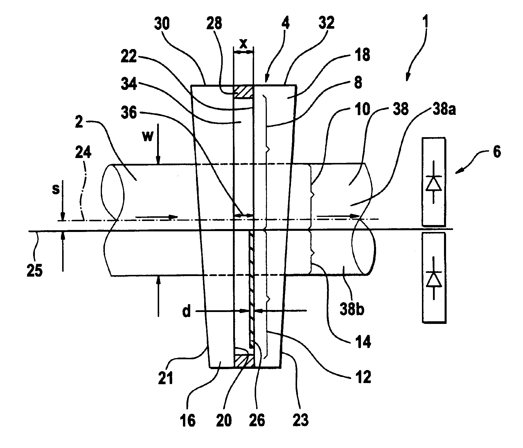
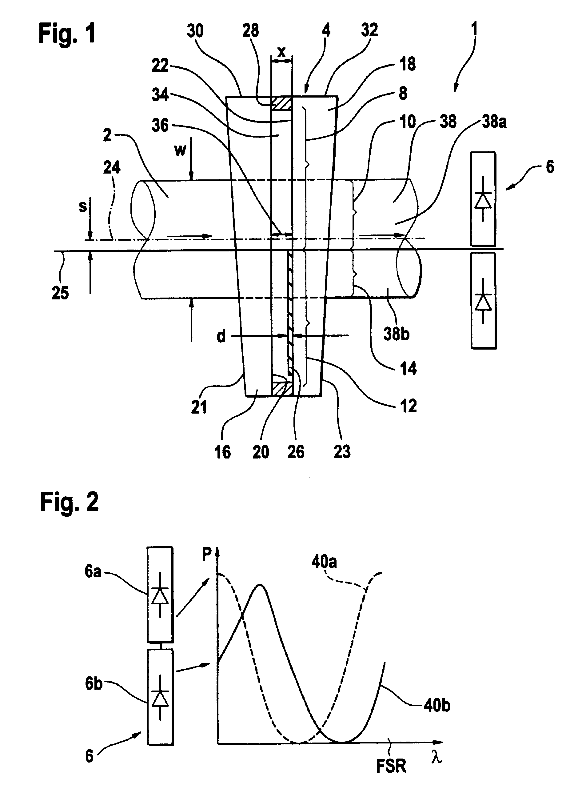
[0030]Referring now in greater detail to the drawings, FIG. 1 shows a wavemeter for measuring a wavelength λ of an optical laser beam 2 having a width W. The wavemeter 1 comprises an interference element-4 (e.g., a split elalon 4), a power detector 6 detecting the optical power of the laser beam 2, and an allocator (not shown) allocating a wavelength to said detected optical power.

[0031]The split etalon 4 has a first section 8 providing a first path for a first part 10 of the light beam 2, the first path having a first interference—effective optical length x. The split etalon 4 has a second section 12 providing a second path for a second part 14 of the light beam 2, the second path having a second interference—effective optical length l=x−d, where d≈λ / 8 of the expected wavelength λ of the laser beam 2. Since the expected wavelength λ in optical communication networks is typically 850-1650 nm the value of d can vary between 100 nm and 210 nm when the wavemeter 1 of FIG. 1 is used as ...


PUM


Abstract

A wavemeter for determining a wavelength of an incident optical beam comprises four optical components, each being arranged in the incident optical beam or in a part of it, providing a path with a respective effective optical length, and generating a respective optical beam with a respective optical power depending on the wavelength of the incident optical beam. The optical powers oscillate periodically with increasing wavelength, and a phase shift of approximately pi/2 is provided between two respective pairs of the four optical components. Respective power detectors are provided, each detecting a respective one of the optical powers. A wavelength allocator is provided for allocating a wavelength to the incident optical beam based on the wavelength dependencies of the detected first, second, third, and fourth optical powers.

Description

BACKGROUND OF THE INVENTION[0001]The present invention relates to wavemeters for determining a wavelength of an optical beam.[0002]Etalons are interference elements for the interference of light. To interfere light an etalon is arranged in an optical beam of the light to be measured or in a part of this beam and the etalon generates an optical signal, whose optical power depends on the wavelength of the optical beam to be measured.[0003]Etalons show a dependency of the generated optical power from the wavelength of the incident optical beam. Generally, an etalon shows a dependency of the generated optical power versus wavelength, which can be described by the use of the Airy formulas. After calibration, the optical power can be measured by use of a photo detector and the wavelength corresponding to the measured optical power is determined.[0004]A stepped etalon providing a transition between the stepped areas is disclosed in EP-A-1081474. A variable wavelength light filter based on ...

Claims


Application Information

Patent Timeline
Patent Type & Authority Patents(United States)
IPC IPC(8): G01J3/12G01J3/26G01J9/00G01J9/02H01S5/00H01S5/0687
CPCG01J3/26G01J9/0246H01S5/0687
Inventor NEBENDAHL, BERNDSCHMIDT, ANDREASJAEGER, MATTHIAS
Owner AGILENT TECH INC
Why Eureka
Try Eureka