
Tool device for rotary knives

a tool device and rotary knife technology, applied in fish processing, meat processing plants, poultry processing, etc., can solve the problems of increasing the risk of injury, reducing the productivity of meat slicing operations, and requiring operators to perform considerable efforts. achieve the effect of easy meat slicing, increased productivity of operations, and limited physical effor

Inactive Publication Date: 2005-09-06
LGR EQUIP DI GRAZIANO RONCAGLIA
View PDF13 Cites 28 Cited by
  • Summary
  • Abstract
  • Description
  • Claims
  • Application Information

AI Technical Summary

Benefits of technology

[0014]The aim of the present invention is to eliminate the above-noted drawbacks of the prior art, by providing a tool for rotary knives that allows to perform meat slicing processes easily and with limited physical effort and to increase the productivity of these operations.
[0015]Within this aim, an object of the present invention is to provide a tool that is simple, relatively easy to provide in practice, safe in use, effective in operation, and of a relatively low cost.

Problems solved by technology

However, the use of these knives forces the operator to perform considerable efforts, especially in view of the fact that the meat to be processed is stored in refrigerating rooms at low temperature and therefore offers considerable resistance to cutting.
As working hours go by, the increasing tiredness of the operator causes an increase in the risk of injury, slows down work and distinctly reduces the productivity of the operator.
Moreover, the use of manual knives requires considerable experience and skill on the part of operators in order to contain the production of waste caused for example by imperfect cuts and in order to reduce the danger of accidents at work.
However, said rotary knives do not allow to slice pieces of meat, i.e., to perform transverse cuts and form slices.
However, these pneumatic knives also are not free from drawbacks, including the fact that the high rate at which the blades perform the cutting stroke can cause unpleasant aching and tingling in the hand and arm of the operator and that their overall weight, particularly for knives with a plurality of blades, makes them awkward to use for prolonged periods.

Method used


Image

  • Tool device for rotary knives
  • Tool device for rotary knives
  • Tool device for rotary knives

Examples


Embodiment Construction

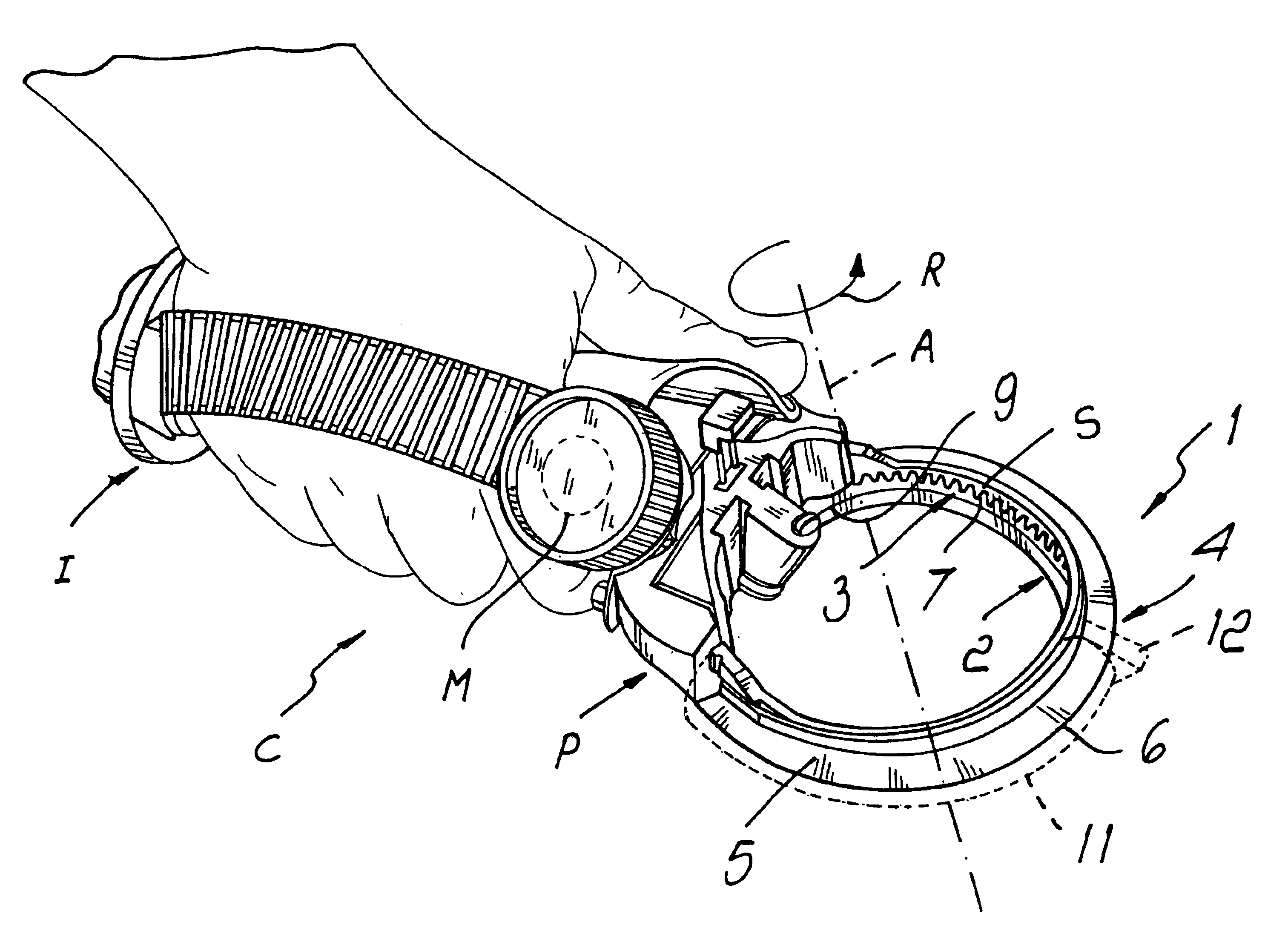
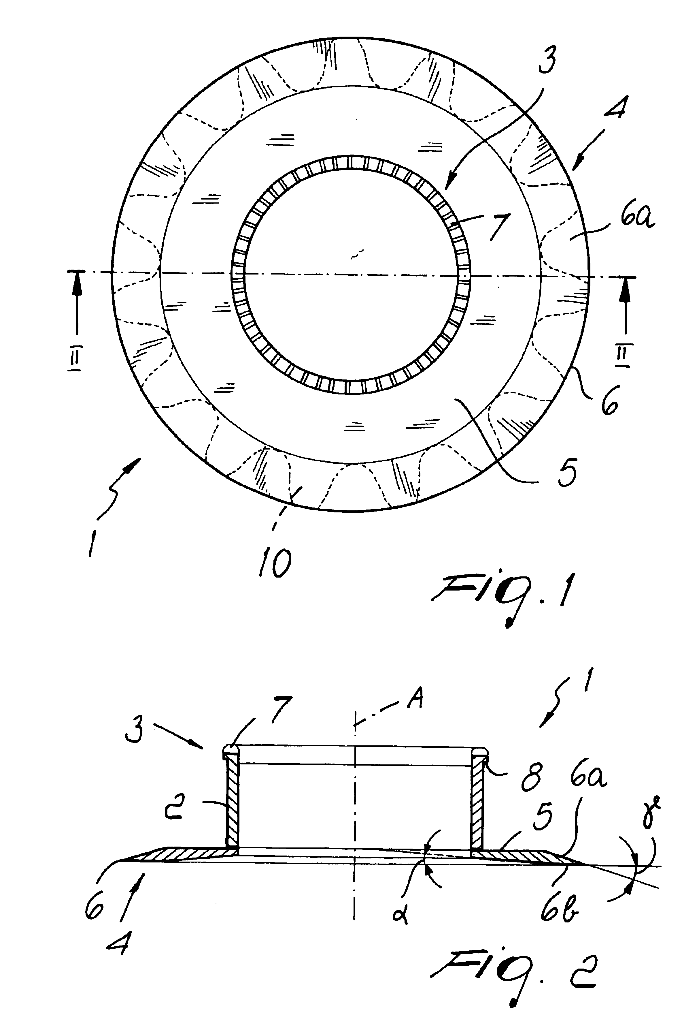
[0021]With reference to the figures, the reference numeral 1 generally designates a tool for rotary knives.

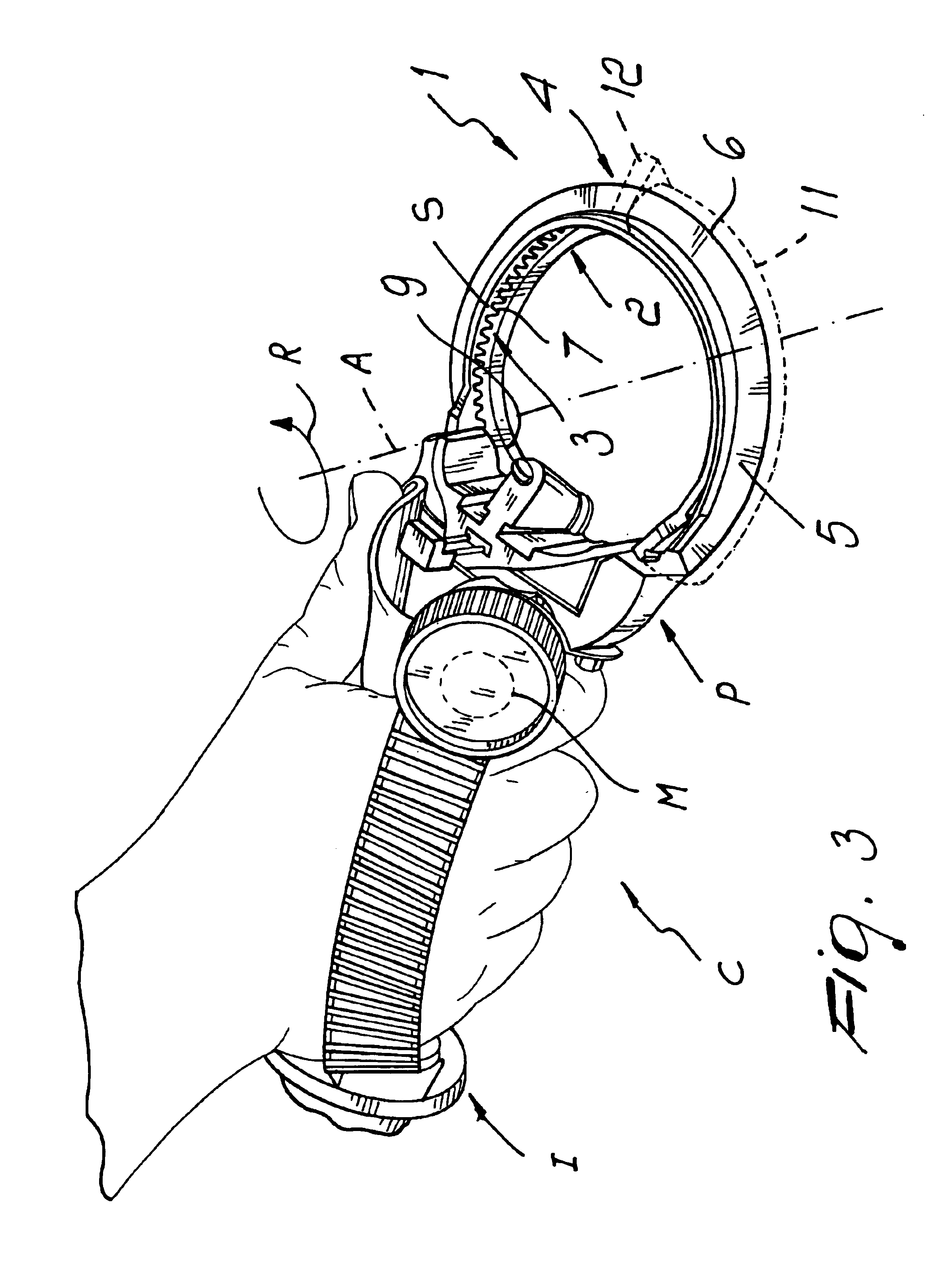
[0022]The tool 1 is designed to be applied to a conventional rotary knife C, which is shown partially in FIG. 3 and is of the type that comprises a handle I that is internally hollow and is associated at one end with a tool supporting assembly P.

[0023]The knife C further comprises conventional actuation means that are adapted to turn about a rotation axis A the tool 1 with respect to the tool supporting assembly P.

[0024]The rotation axis A is arranged transversely to the handle I and coincides with the axis of symmetry of the tool 1.

[0025]The tool supporting assembly P, not shown in detail because it is of a conventional type, is provided with a first portion that comprises a contoured claw, which is fixed to the handle I and is associated with a circular support S of the tool 1, and with a second portion that is constituted by a movable claw, which is associated with the fixed...


PUM


Abstract

A tool device for rotary knives of the type that comprises a handle associated with a tool supporting assembly and an actuation for the rotary actuation of the tool with respect to the tool supporting assembly, the tool comprising a substantially tubular coupling body that is associable with the tool supporting assembly and being provided with a coupling to the actuation, and a cutter that is rigidly associated with the body and is arranged so as to protrude substantially radially with respect to the body.

Description

BACKGROUND OF THE INVENTION[0001]The present invention relates to a tool device for rotary knives particularly for cutting animal meat.[0002]In the field of animal meat butchering and processing it is known to use manual knives provided with variously shaped blades in order to perform, for example, cutting, fat removal and boning of the meat.[0003]However, the use of these knives forces the operator to perform considerable efforts, especially in view of the fact that the meat to be processed is stored in refrigerating rooms at low temperature and therefore offers considerable resistance to cutting.[0004]As working hours go by, the increasing tiredness of the operator causes an increase in the risk of injury, slows down work and distinctly reduces the productivity of the operator.[0005]Moreover, the use of manual knives requires considerable experience and skill on the part of operators in order to contain the production of waste caused for example by imperfect cuts and in order to r...

Claims


Application Information

Patent Timeline
Patent Type & Authority Patents(United States)
IPC IPC(8): B26B25/00
CPCB26B25/002
Inventor RONCAGLIA, GRAZIANO
Owner LGR EQUIP DI GRAZIANO RONCAGLIA
Learn More