
Method and apparatus for eliminating a parting line witness mark from a molded part

a witness mark and molded part technology, applied in the direction of turning apparatus, molds, food shaping, etc., can solve the problems of increasing mold maintenance costs, unavoidable events, and increasing the cost of molds

Inactive Publication Date: 2005-09-06
MOLD BERNARD
View PDF5 Cites 5 Cited by
  • Summary
  • Abstract
  • Description
  • Claims
  • Application Information

AI Technical Summary

Benefits of technology

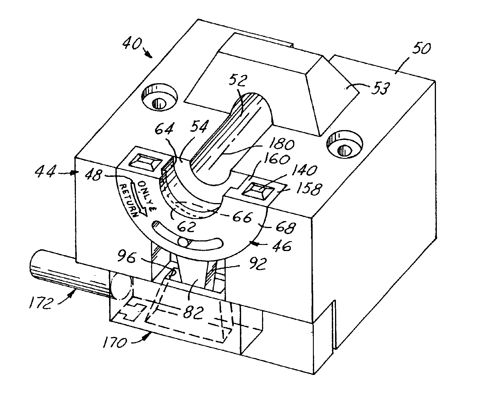
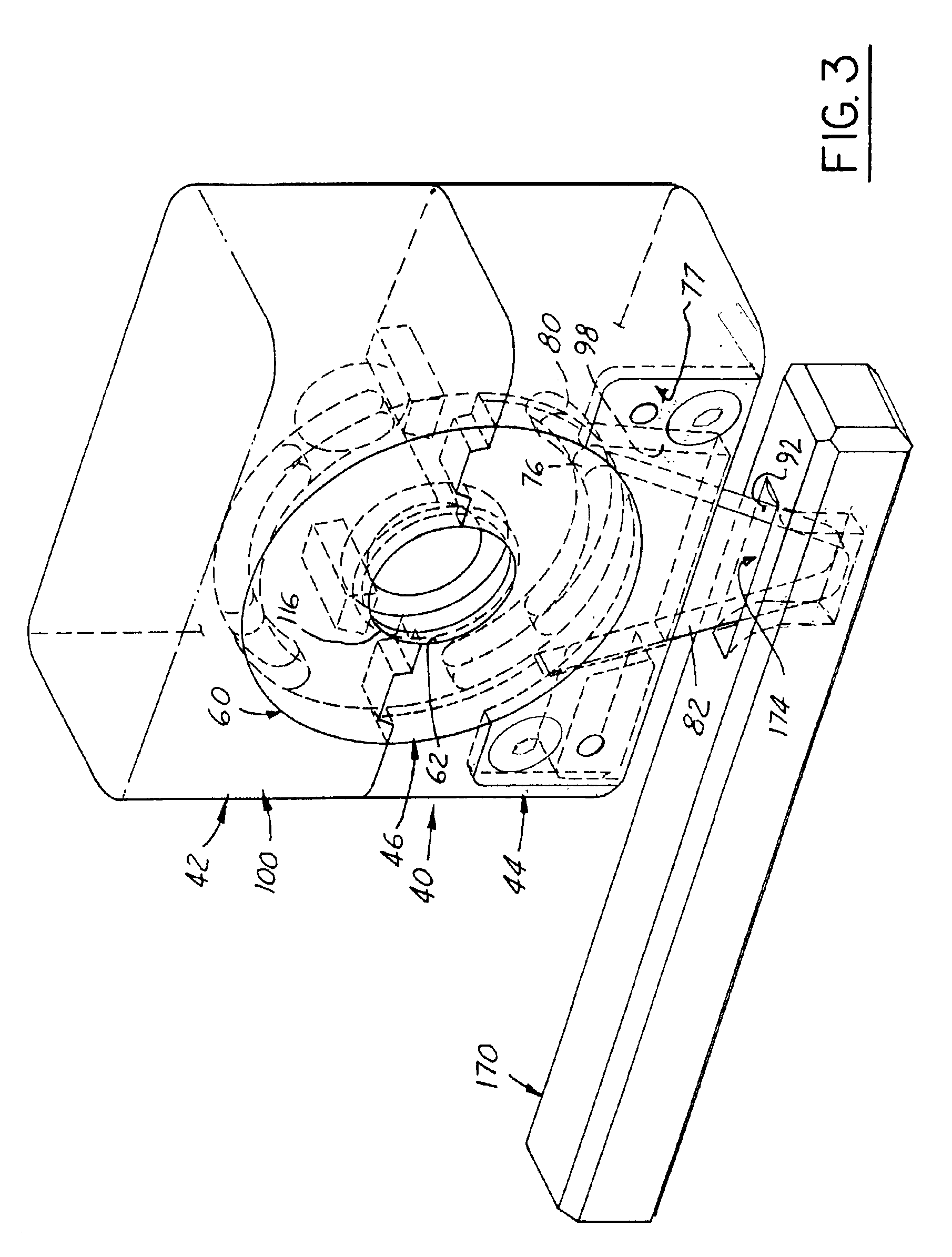
"The present invention provides an improved method and apparatus for molding a sealing surface on a molded part. The sealing surface is formed by a mold part that is molded in separable first and second partable mold halves that mate when closed. The mold halves each have a mold half cavity, which together define the complete mold cavity. The mold includes first and second mold inserts that each have a sub-insert trim wheel component that defines a cooperative mold half cavity. The sub-inserts are rotatably supported in the associated mold half inserts for rotation through a given range of angular travel to position the mold sub-inserts at a second predetermined position. The sub-inserts are then rotated to remove any parting line flash that might otherwise remain on the sealing surface. The mold halves are opened to remove the completed molded part. The invention allows for the formation of a smooth sealing surface and ensures a proper fitting of a sealing member, such as an O-ring."

Problems solved by technology

This parting line gap is sometimes used as a venting space for the mold cavity, but in any event is unavoidable.
Such parting line “witness marks” are often considered acceptable but unavoidable in the molding and casting art, although in some cases they are particularly or completely removed by various post-molding finishing operations such as machining, grinding, tumbling, etc. if the expense of such removal is deemed justified or necessary to meet the end use requirements for the cast or molded object.
However, this increases the cost of molds substantially.
Reducing or eliminating parting line flash by tight fit of the mold parts at the parting line also greatly increases mold maintenance costs since tool wear and use tends to open up the parting line clearances or gap, thereby requiring that the mold parts be taken out of service and reworked in order to bring them back to original tolerance specifications.
Since the sealing function of the O-ring requires that it be pressed or compressed tightly against the sealing surface of the part throughout the entire circumferential engagement between the seal and the part sealing surface, the existence of a transverse ridge on the sealing surface, such as that resulting from the presence of a parting line witness mark, cannot be tolerated.
In addition, the existence of such a parting line flash ridge often presents a sharp edge which will cut into the sealing material and also destroy its effectiveness as a seal.
However, with some materials and at some higher working pressures, material will still flash (i.e., escape from the mold cavity into the minute clearance between the mold parts at the parting line plane) even when the parting line gap is only somewhere between three and five ten thousandths of an inch.
However, as the mold is cycled, it tends to wear and hence this original tight gap tolerance zone gradually opens up, and mold rework then becomes necessary.
The economics of low volume runs often requires that this be a manual operation entailing significant labor costs as well as causing quality control problems in attempting to achieve a smooth finish sealing surface on the part within acceptable tolerance limits.

Method used


Image

  • Method and apparatus for eliminating a parting line witness mark from a molded part
  • Method and apparatus for eliminating a parting line witness mark from a molded part
  • Method and apparatus for eliminating a parting line witness mark from a molded part

Examples


Embodiment Construction

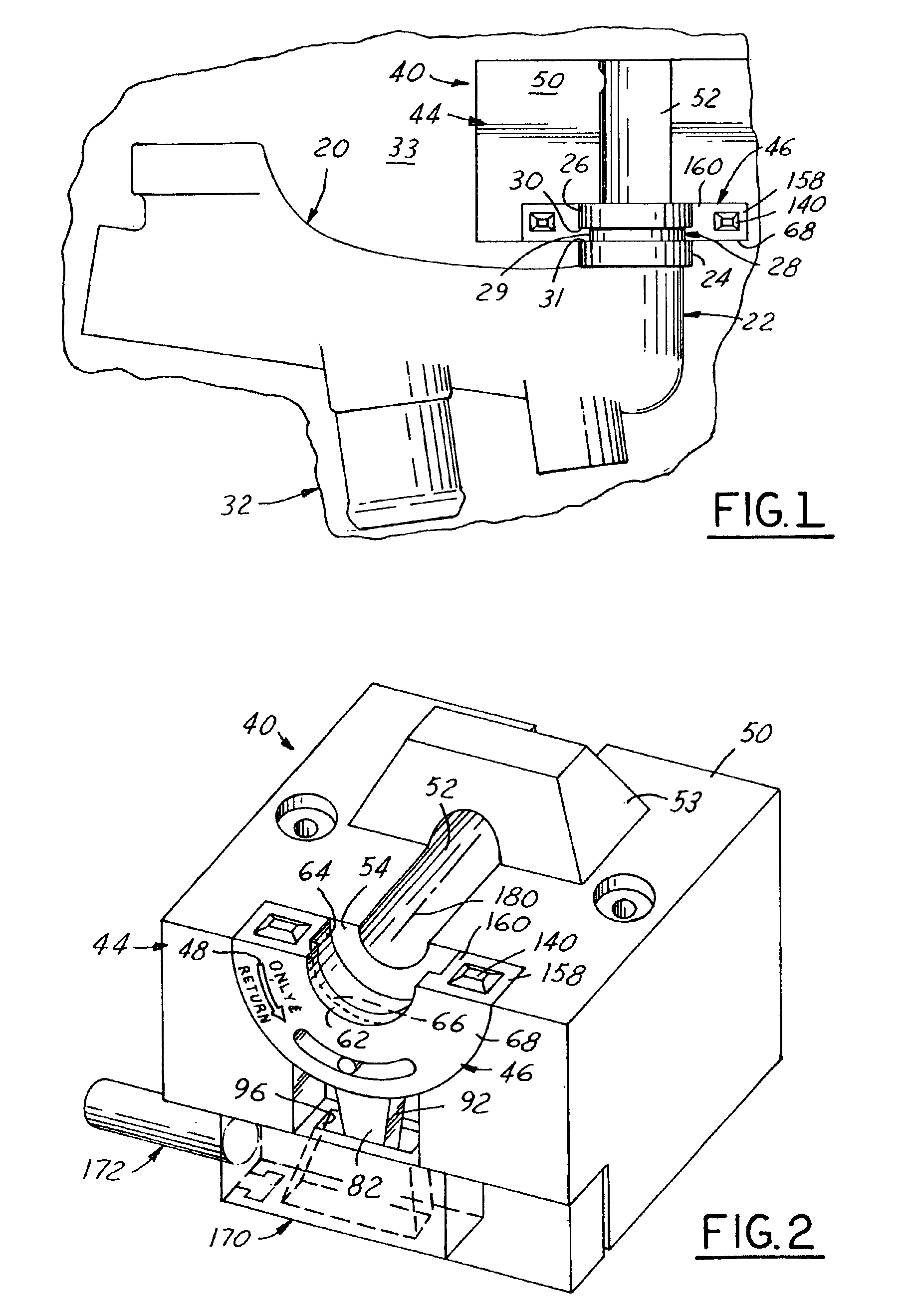
[0031]Referring in more detail to the accompanying drawings, FIG. 1 illustrates the improved method and apparatus of the invention in one preferred but exemplary first embodiment employed in the plastic injection molding of an automotive engine cooling system conduit 20. One elbow 22 of conduit 20 terminates in a pair of axially spaced apart cylindrical ribs 24 and 26 defining therebetween an external groove 28 dimensioned and configured as a sealing surface of revolution for receiving an annular O-ring seal therein (not shown) for providing a liquid-tight seal when the ribs 24, 26 are inserted into the bore of an associated engine block coolant port (not shown).

[0032]O-ring groove 28 thus has, in the illustrated exemplary embodiment, a cylindrical bottom wall 29 flanked by two radially extending sidewalls 30 and 31 to thereby form an external square-cut type sealing groove. In operative assembly, the O-ring (not shown) is designed to fit relatively snuggly in sealing groove 28 in i...


PUM

PropertyMeasurementUnit
acute angleaaaaaaaaaa
solidification strengthaaaaaaaaaa
internal diameteraaaaaaaaaa

Abstract

Method and apparatus for molding a sealing surface of revolution on a molded part in first and second partable mold halves that mate at a major parting line plane. First and second mold inserts each have a sub-insert trim wheel component shaped to mold form the sealing surface of revolution when closed at a minor parting line plane. The sub-inserts are rotatable between a position flush with the major parting line plane and a starting position angularly offset therefrom. The mold cavity is filled with liquid molding material that is allowed to harden to at least a self-sustaining solidification strength. The sub-inserts are then rotated to thereby move any minor parting line flash toward a position angularly offset from their starting position. This rotation causes any parting line flash that might otherwise remain on the sealing surface to be removed from attachment to, and / or smeared smooth along, such surface.

Description

[0001]This is a regular United States Utility patent application filed pursuant to 35 U.S.C. § 111 (a) and claiming the benefit under the provision of 35 U.S.C. §119 (e)(i) of the priority of U.S. Provisional Utility Patent Application Ser. No. 60 / 316,091 filed Aug. 30, 2001 pursuant to 35 U.S.C. §111 (b).FIELD OF THE INVENTION[0002]This invention relates to methods and apparatus for molding objects in a separable, two-part permanent mold wherein a parting line plane of the mold intersects the part being molded in the mold cavity, and more particularly to injection molding of plastic parts in a two-part separable mold of the foregoing character.BACKGROUND OF THE INVENTION[0003]In the manufacture of products and components of various complex shapes by molding or casting wherein a mold cavity is infilled with a molding or casting material in a liquid state and allowed to harden in the mold cavity, in most instances a separable mold is used that is made up of “core” and “cavity” half m...

Claims


Application Information

Patent Timeline
Patent Type & Authority Patents(United States)
IPC IPC(8): B29C45/00B29C45/56
CPCB29C45/0025B29C45/5605
Inventor BERNARD, EDWARD HELMUT
Owner MOLD BERNARD
Learn More