Brushless motor and hermetic compressor assembly including the same motor

Active Publication Date: 2005-09-06
PANASONIC CORP +1
View PDF19 Cites 12 Cited by
  • Summary
  • Abstract
  • Description
  • Claims
  • Application Information

AI Technical Summary

Benefits of technology

[0023]According to still another aspect of the present invention, there is provided an hermetic compressor including the above-described brushless motor. The leak current from the coil ends in this hermetic compressor can be re

Problems solved by technology

Also, an electric motor having a stator with concentrated windings (hereinafter referred to as “concentrated-winding motor”) can be reduced in coil end hei

Method used


Image

  • Brushless motor and hermetic compressor assembly including the same motor
  • Brushless motor and hermetic compressor assembly including the same motor
  • Brushless motor and hermetic compressor assembly including the same motor

Examples


embodiment 1

(Embodiment 1)

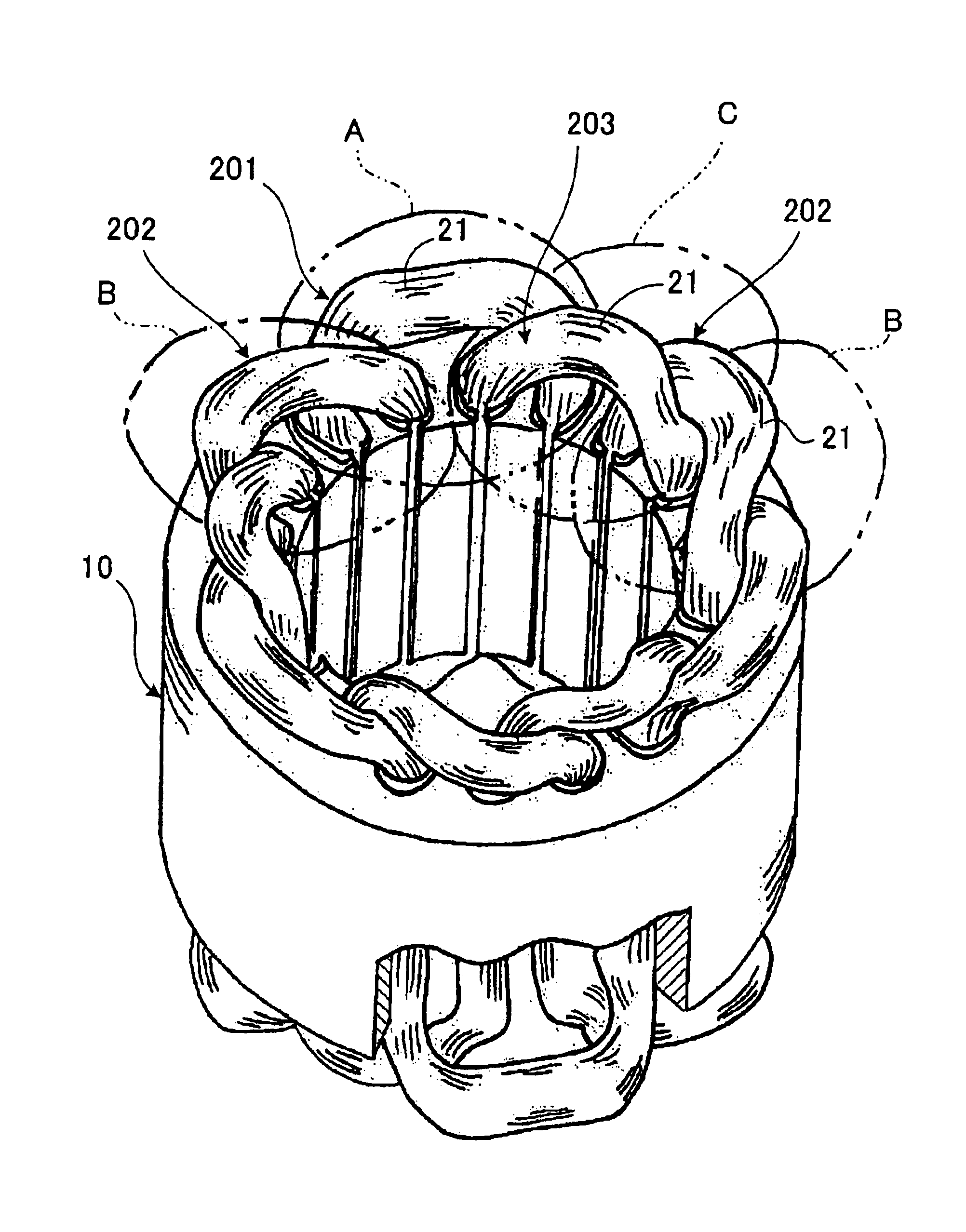
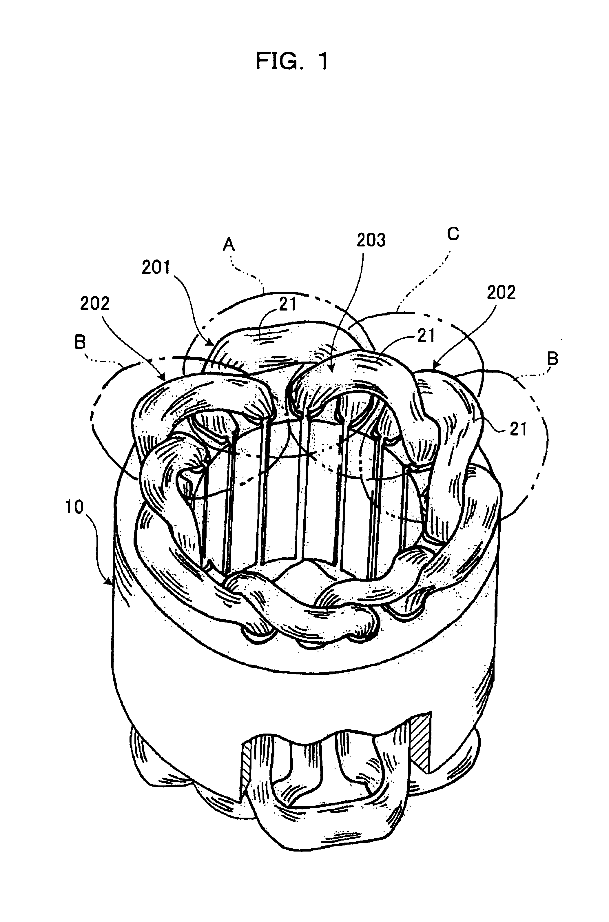
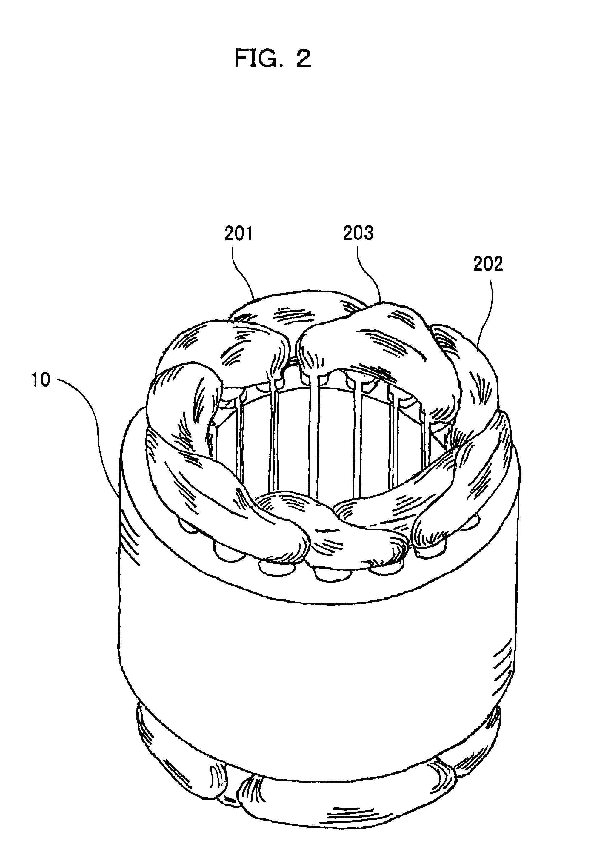
[0042]FIG. 1 shows the arrangement of coils of a stator in a three-phase full-pitch-winding brushless motor in which the number of poles of a rotor is 6 and the number of slots in the stator is 18. FIG. 15 shows stator 10 including eighteen teeth 11 and six pole elements 12.

[0043]Coil ends of the coils corresponding to the phases are arranged on a stator core end surface as described below. In a place where a second coil 202 and a third coil 203 are inserted in slots 11 adjacent to each other (hereinafter referred to as “place A” indicated by a symbol “A” in FIG. 1), a first coil 201 is located outside the second coil 202 and the third coil 203. In a place where the first coil 201 and the third coil 203 are inserted in slots 11 adjacent to each other (hereinafter referred to as “place B” indicated by a symbol “B” in FIG. 1), the second coil 202 is located from inside of the first coil 201 to outside of the third coil 203. In a place where the first coil 201 and the sec...

embodiment 2

(Embodiment 2)

[0048]Another embodiment of the present invention will be described, which is a three-phase full-pitch-winding brushless motor in which the number of poles of a rotor is 4 and the number of slots in a stator is 12.

[0049]FIG. 4 is a diagram showing the coil arrangement of the present invention in the three-phase full-pitch-winding brushless motor having four poles and twelve slots. FIG. 5 shows an example of a conventional three-phase full-pitch-winding brushless motor having four poles and twelve slots (a brushless motor having a configuration described in Japanese Patent Laid-Open No. 2-221688).

[0050]In the conventional motor shown in FIG. 5, the coils are concentrically arranged and two coil ends exist concentrically on the left and right sides of one coil, as in the case of the short-pitch concentrically distributed windings described above with reference to FIG. 14. Therefore, the left and right regions required in shaping the above-described shaping mechanism are ...

embodiment 3

(Embodiment 3)

[0052]A method of manufacturing windings in the above-described (Embodiment 1) three-phase full-pitch-winding brushless motor having six poles and eighteen slots, particularly windings on the stator will next be described.

[0053]The process of manufacturing the windings on the stator consists mainly of five steps, as shown in FIG. 6.

[0054]The first step is an annular coil winding step in which an annular winding is formed with respect to each phase. FIG. 7 shows an example of this step. A reel framework 41 is a rotor and has movable reel members 42. As the reel framework 41 rotates, a coil 20 supplied through a coil supply nozzle 43 is wound around the movable reel members 42 to form an annular coil. The setting of the length of the coil and the configuration of the coil in this step are important factors in obtaining a lower coil end.

[0055]The second step is a star coil forming step in which the periphery of the annular coil formed in the first step is formed into a pr...


PUM


Abstract

A low-vibration/noise brushless motor capable of limiting the height of coil ends, and a low-current-leak hermetic compressor includes the brushless motor. This brushless motor is of a three-phase full-pitch-winding type including a stator having coils (20) inserted in slots in a one coil per one slot manner. Coil ends (21) of the coils (20) are arranged such that the first coil (201) is arranged outside the second and third coils (202, 203) in a place (A) where the second and third coils (202, 203) are inserted in a pair of slots adjacent to each other, the second coil (202) is arranged from inside of the first coil (201) to outside of the third coil (203) in a place (B) where the first and third coils are inserted in another pair of slots adjacent, and the third coil (203) is arranged inside the first and second coils (201, 202) in a place (C) where the first and second coils (201, 202) are inserted in still another pair of adjacent slots. The coil ends (21) are shaped in the axial direction.

Description

FIELD OF THE INVENTION[0001]The present invention relates to a small-size, low-vibration / noise brushless motor for driving an air conditioner fan and the like, and to be mounted in refrigerators, motor vehicles and other various machines, and to an hermetic compressor including the same motor.BACKGROUND OF THE INVENTION[0002]The challenge to reduce the size of a machine and vibrations / noise generated in the machine is an essential object to be attained in the development of the machine, and developers of machines including hermetic compressors are naturally confronted with such a challenge.[0003]In the development of an electric motor, reducing the overall height of a stator constituting the motor is a means for achieving reduction in size. In a stator with short-pitch concentrically distributed windings such as shown in FIG. 14, the height of coil ends is limited in such a manner that coils 20 are shaped in the axial direction after the coils 20 have been inserted in slots of a sta...

Claims


Application Information

Patent Timeline
IPC IPC(8): F04B35/00F04B35/04H02K3/12H02K15/00F04B39/00H02K3/28H02K21/16H02K29/00
CPCF04B35/04H02K3/12H02K15/0037H02K3/28
Inventor YAMAZAKI, AKIHIKOOKUYAMA, SHINICHISEKI, YASUTAKEMURAKAMI, HIROSHIKATAOKA, HISAKAZUMORINO, OSAAKIODACHI, YASUHARUSUITOU, KEN
Owner PANASONIC CORP
Why Eureka
Try Eureka