Long-life high-pressure discharge lamp and lamp unit using same

Active Publication Date: 2005-09-06
ALLIED MATERIAL +1
View PDF12 Cites 3 Cited by
  • Summary
  • Abstract
  • Description
  • Claims
  • Application Information

AI Technical Summary

Benefits of technology

[0011]In view of the problems in the prior art as described above, it is an object of the present invention to provide a high-pressure discharge lamp which is capable of maintaining the “short arc” condition for a long time.
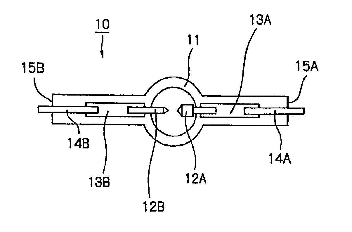
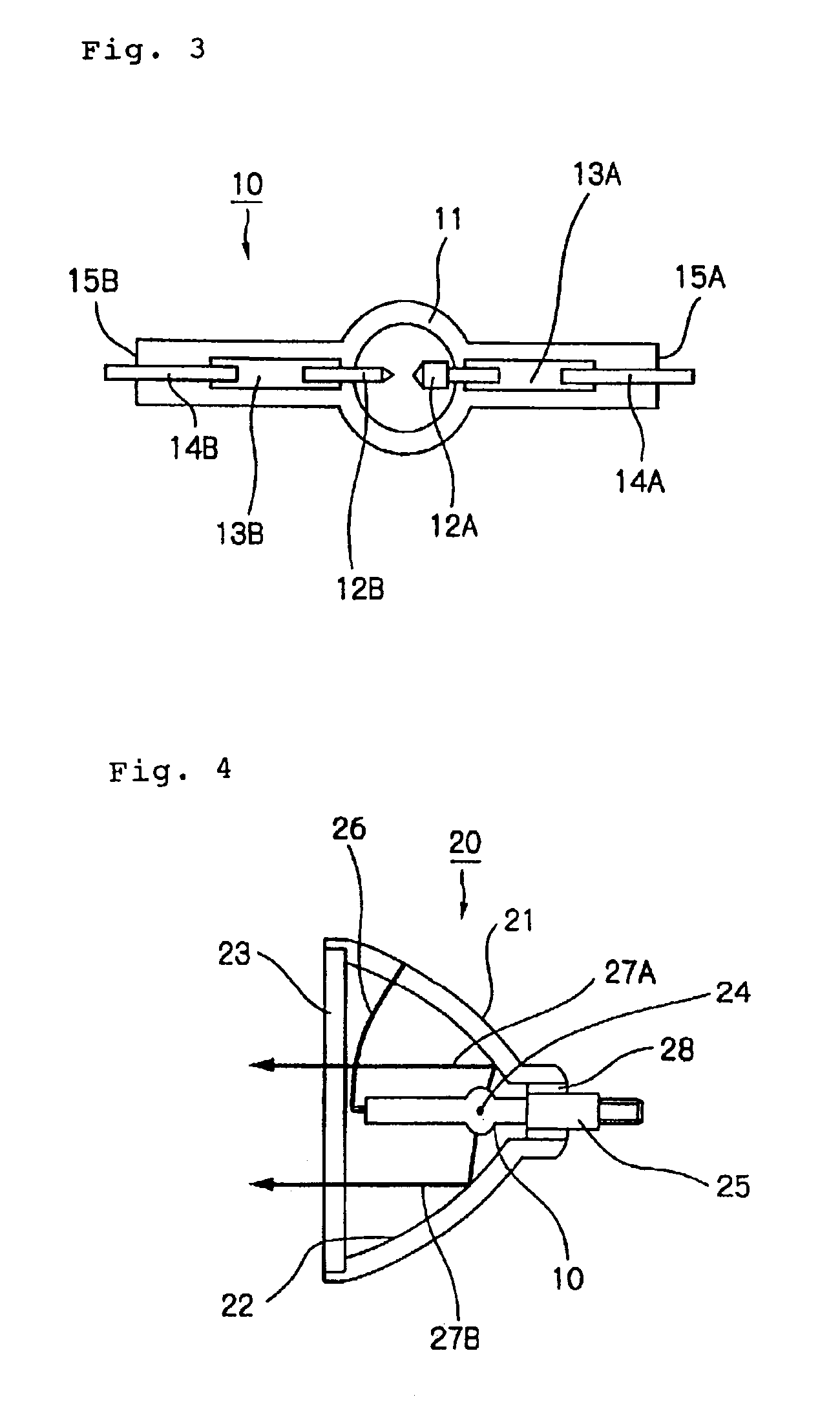
[0012]The present invention provides a high-pressure discharge lamp which includes a lamp tube made of quartz glass and hermetically sealed, a pair of opposing electrodes inserted into the lamp tube, and at least mercury and a halogen gas filled in the lamp tube. One of the pair of electrodes is made of a tungsten material which contains more than 10 ppm of one of Co and Ni which belong to iron-group materials; or a tungsten material which contains in total 20 ppm or more of at least two of Fe, Co and Ni which belong to iron-group materials; or a tungsten material which contains 20 ppm or more of Fe. Thus, the high-pressure discharge lamp of the present invention exhibits a high efficiency of a “halogen cycle” in which the tungsten in the electrode material, which evaporates during discharge, returns to the electrodes without sticking to the inner wall of the lamp tube and therefore more efficiently deposits on the leading ends of the electrodes, as compared with a conventional high-pressure discharge lamp which employs electrodes made of a tungsten material that contains 10 ppm or less of one of Fe, Ni and Co, or contains 10 ppm or less of Fe, Ni and Co in total. Thus, the present invention can extend the lifetime of the “short arc” high-pressure discharge lamp because the leading ends of the electrodes are apparently less worn to limit the expanse of the inter-electrode distance. Moreover, a lamp unit can be designed such that the light emission center of the high-pressure discharge lamp is positioned at the focal point of a parabolic surface of a reflector, for use as a light source of a liquid crystal projector, by way of example. The resulting product, i.e., lamp unit can provide a high incident efficiency to an optical system.

Problems solved by technology

However, since actual light sources are not ideal point sources but have a certain size, light reflected from the reflector has an expanse, resulting in an incident efficiency to the optical system which is lower than that of an ideal point source.
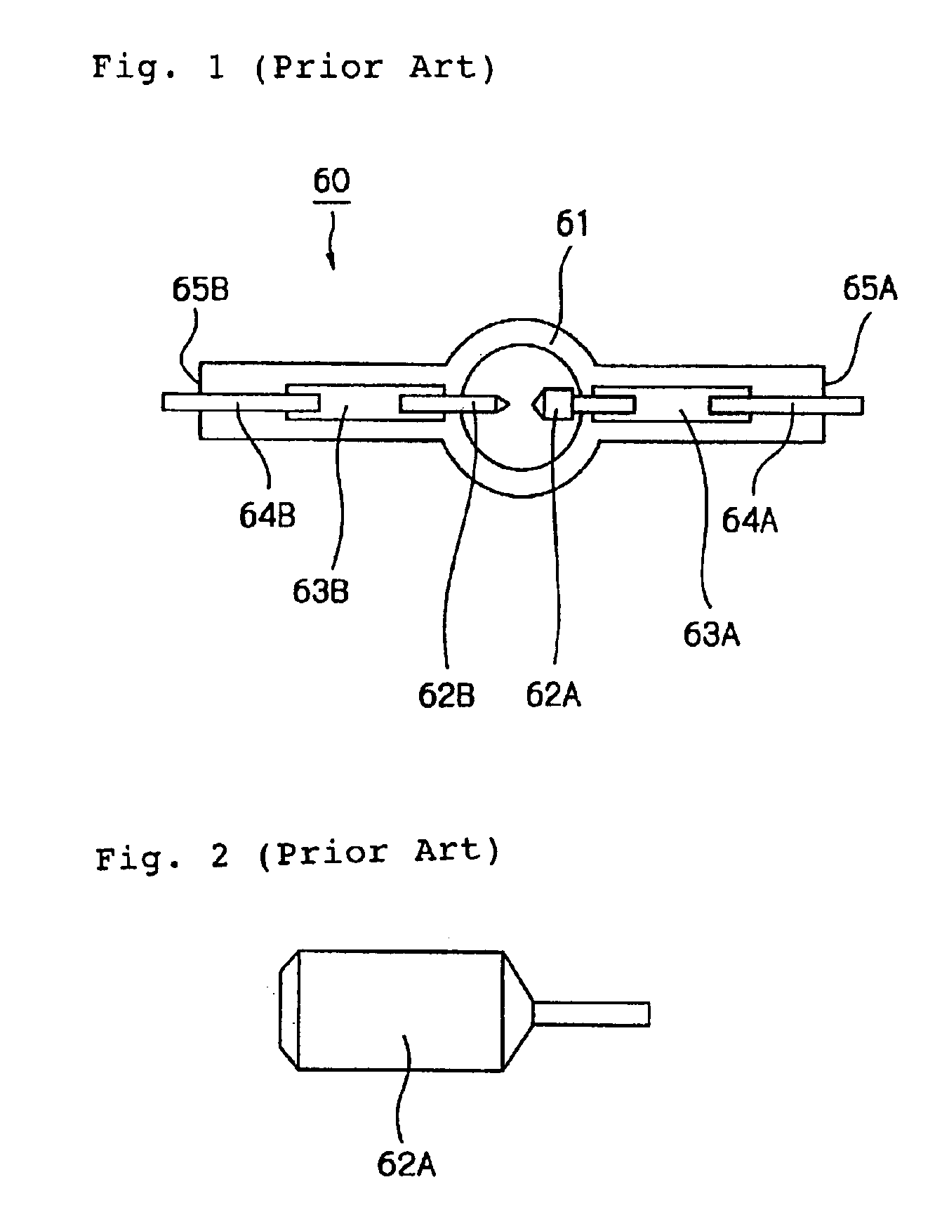
However, when the conventional high-pressure discharge lamp is operated for a long time, the following problems occur. FIG. 2 illustrates the shape of the anode after the conventional direct-current high-pressure discharge lamp was operated for 2,000 hours.
Further, an increasingly blunt angle at the leading end of the anode causes the discharge plasma to radially expand, in contrast to the point source, resulting in a lower incident efficiency to the optical system.
However, even with these proposals, it is difficult to maintain for a long time the “short arc” condition with a short inter-electrode distance and a small discharge plasma, as is similar to the conventional high-pressure discharge lamp described above.
Consequently, a projector designed for a “short arc” high-pressure discharge lamp suffers from a significantly reduced incident efficiency to an optical system and a problem of a short product life.

Method used


Image

  • Long-life high-pressure discharge lamp and lamp unit using same
  • Long-life high-pressure discharge lamp and lamp unit using same
  • Long-life high-pressure discharge lamp and lamp unit using same

Examples


examples

[0038]FIG. 6 shows changes in the inter-electrode distance over time, measured by the radiography in a life test conducted for the direct-current high-pressure discharge lamp according to the present invention which has the anode made of a tungsten material that contains more than 10 ppm of Ni, and a conventional direct-current high-pressure discharge lamp which has an anode made of a tungsten material that contains 10 ppm or less of Ni. As can be seen from the graph, when the initial inter-electrode distance is 1 mm, the inter-electrode distance extends to approximately 1.4 mm in the conventional direct-current high-pressure discharge lamp after 2,000 hours, whereas the inter-electrode distance extends merely to approximately 1.2 mm in the direct-current high-pressure discharge lamp according to the present invention.

[0039]FIG. 7 illustrates the shape of the anode in the direct-current high-pressure discharge lamp according to the present invention after the lamp has been used for ...


PUM


Abstract

A high-pressure discharge lamp comprises a lamp tube made of quartz glass and having a central portion formed in a spherical shape, and a pair of opposing tungsten electrodes inserted into the lamp tube. At least one of the tungsten electrodes is made of a tungsten material which contains more than 10 ppm of one of Co and Ni, or 10 ppm of Co and Ni in total, or a tungsten material which contains 20 ppm or more of at least two of Fe, Co and Ni in total, or a tungsten material which contains 20 ppm or more of Fe. Fe, Co and Ni belong to iron-group metals. The inter-electrode distance, i.e., distance between the leading ends of both tungsten electrodes is set to approximately 1-2 mm or less.

Description

BACKGROUND OF THE INVENTION[0001]1. Field of the Invention[0002]The present invention relates to high-pressure discharge lamps including a metal halide lamp, an ultra high-pressure mercury lamp and the like, and more particularly to a high-pressure discharge lamp which operates in a condition close to a point source.[0003]2. Description of the Related Art[0004]FIG. 1 illustrates prior art direct-current high-pressure discharge lamp 60 which is described below. A pair of opposing tungsten electrodes 62A, 62B are inserted into lamp tube 61 made of quartz glass. In direct-current high-pressure discharge lamp 60 illustrated in FIG. 1, both tungsten electrodes 62A, 62B have different shapes. In consideration of tungsten which becomes worn due to evaporation during a discharge, tungsten electrode 62A, which acts as an anode in the operation of the discharge lamp, is designed to have larger dimensions than tungsten electrode 62B which acts as a cathode. Tungsten electrodes 62A, 62B are mad...

Claims


Application Information

Patent Timeline
IPC IPC(8): F21S2/00H01J61/86H01J61/88H01J61/06H01J61/073H01J61/84H01J17/04H01J17/20H01J17/02F21Y101/00
CPCH01J61/0735H01J61/86
Inventor AOKI, YASUSHIKATOH, MASAHIRO
Owner ALLIED MATERIAL
Why Eureka
Try Eureka