Inverter device

a voltage-fed inverter and inverter technology, which is applied in the direction of electronic commutators, motor/generator/converter stoppers, dynamo-electric converter control, etc., can solve the problems that the solution cannot resist high-speed rotation and the conventional system is not applicable to the motor driven at a high speed, so as to achieve the effect of large inverter device capacity and economical inverter devi

Inactive Publication Date: 2005-09-06
TOSHIBA MITSUBISHI-ELECTRIC IND SYST CORP
View PDF19 Cites 22 Cited by
  • Summary
  • Abstract
  • Description
  • Claims
  • Application Information

AI Technical Summary

Benefits of technology

[0016]As a result, it is possible to achieve a large capacity of inverter device easily, and an economical inverter device is obtained.

Problems solved by technology

Moreover, since the resolver 10 is used for the purpose of detecting a position of an armature of the alternating current motor 9, the resolver cannot resist high-speed rotation of the alternating current motor 9, and the conventional system is not applicable to a motor driven at a high speed.

Method used


Image

  • Inverter device
  • Inverter device
  • Inverter device

Examples


embodiment 1

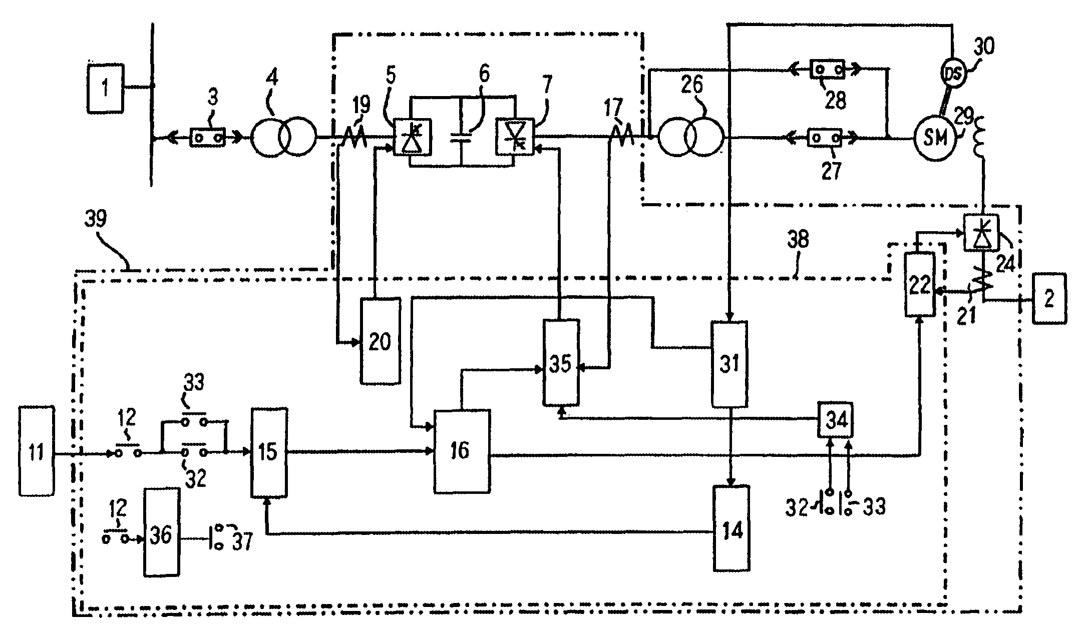
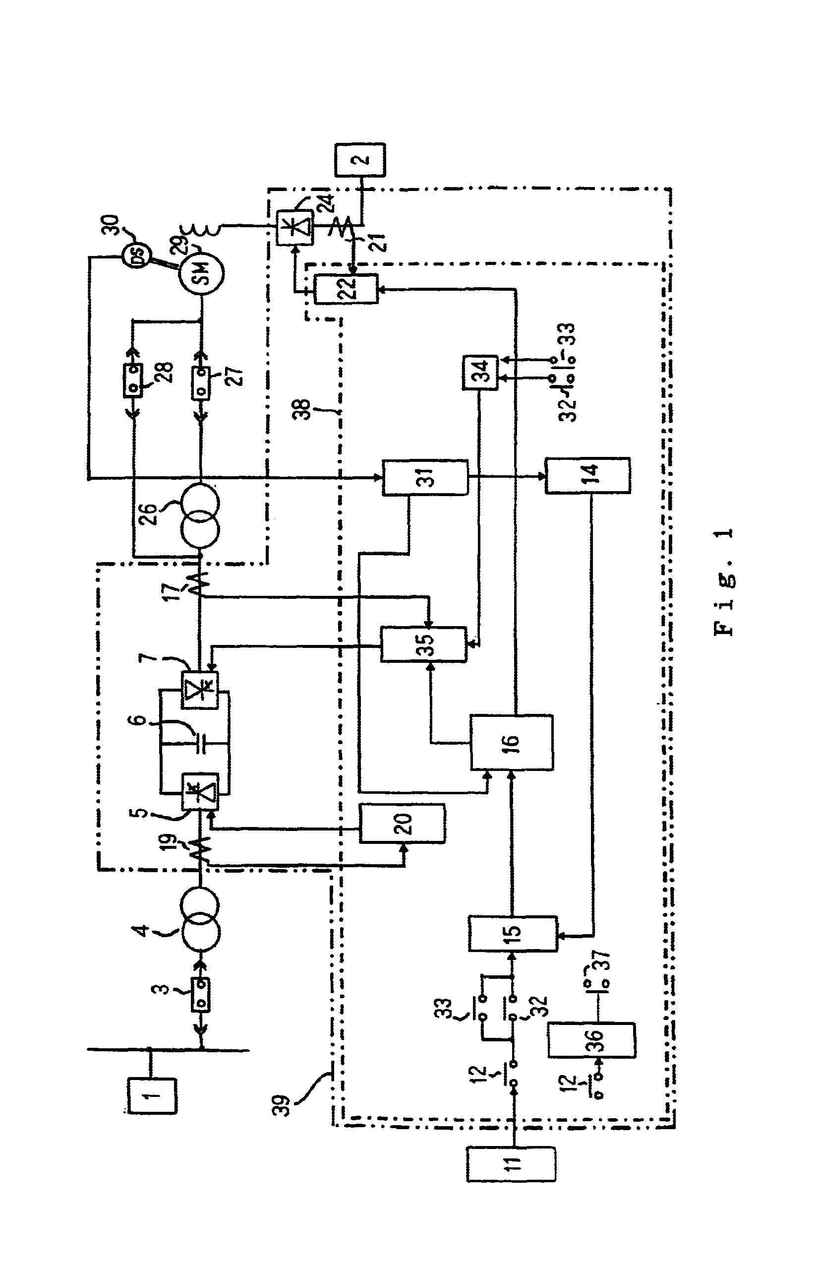
[0031]Embodiment 1 of the invention is hereinafter described with reference to FIG. 1. An inverter device according to this Embodiment 1 includes a commercial alternating current power supply 1 for main circuit, a commercial alternating current power supply 2 for field system, a breaker 3, an input transformer 4, a main circuit 5 for power rectification using a semiconductor device (hereinafter referred to as power rectification main circuit), a smoothing capacitor 6, a main circuit 7 for inverse transformation using a semiconductor device (hereinafter referred to as inverse transformation main circuit), an alternating current synchronous motor 29 for high-voltage (hereinafter referred to as alternating current motor), an output transformer 26 for raising voltage interposed between the inverse transformation main circuit 7 and the alternating current motor 29, a breaker 27 connected in series to the output transformer 26, a breaker 28 that is connected to a bypass circuit for bypass...

embodiment 2

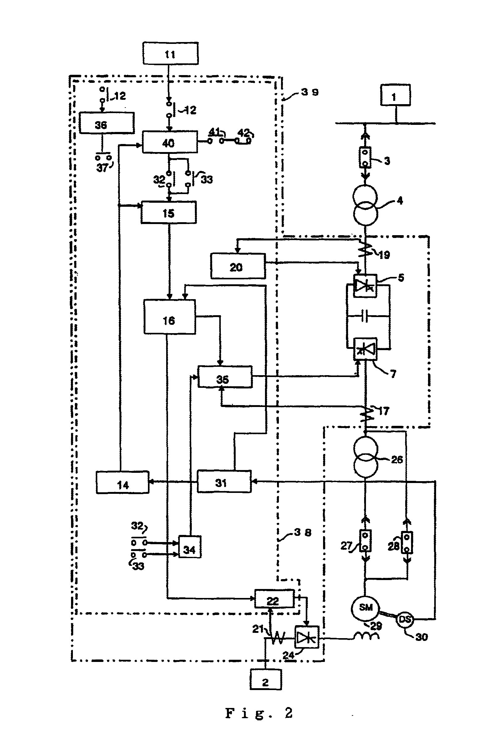
[0039]FIG. 2 is a circuit diagram showing an inverter device according to Embodiment 2 of the invention. The inverter device of this Embodiment 2 is different from the inverter device of Embodiment 1 in the aspect that a speed command gradient generator 40 is used as shown in FIG. 2. A command value of the speed command gradient generator 40 increases (or decreases) gradually with respect to the time base.

[0040]Referring to FIG. 2, the breaker 28 is turned on by an ON signal of the operation command contact 12 of the inverter circuit 39, and the alternating current motor 29 is started through the bypass circuit for bypassing the transformer 26. After passing a predetermined time, the contact 37 is turned on by an output of the timer 36, whereby the breaker 28 is turned off and the breaker 27 is turned on, thus being switched to the circuit for supplying a power to the alternating current motor 29 via the transformer 26. In this switching process, depending upon the operating time re...

embodiment 3

[0042]FIG. 3 shows a circuit diagram of an inverter device according to Embodiment 3 of the invention. In the foregoing Embodiment 1, the contact 37 operated by the timer 36 is used to switch to the circuit with a transformer or to the circuit without any transformer after the operation start command 12 is turned on as shown in FIG. 1. On the other hand, in this Embodiment 3, as shown in FIG. 3, a contact 46 that works when the speed feedback value of the speed detector 14 reaches a speed set by a speed determination circuit 45 turns the breaker 28 off and turns the breaker 27 on, whereby the alternating current motor 29 is brought into normal operation. Other arrangement is the same as that in FIG. 1, and further explanation is omitted here.

[0043]Therefore, in this Embodiment 3, unlike the case of using the timer to follow the speed command value of the outside speed command generator 11, the speed of bringing the motor into normal operation is not changed according to load conditi...


PUM


Abstract

An inverter device capable of smoothly driving an alternating current synchronous motor of large capacity and high-speed rotation is provided. The inverter device includes a power rectification main circuit for converting alternating current power into direct current power and a PWM control inverse transformation main circuit. A transformer raises output terminal of the alternating current power of the inverse transformation main circuit to drive an alternating current synchronous motor. The alternating current motor is started bypassing the transformer and limiting output voltage of the inverse transformation main circuit to a low value through PWM control of the inverse transformation main circuit. After a predetermined time, the bypass circuit is interrupted and switched to a circuit via the transformer, and the output voltage of the inverse transformation main circuit is raised through PWM control of the inverse transformation main circuit, thus the alternating current synchronous motor is brought into normal operation.

Description

BACKGROUND OF THE INVENTION[0001]1. Field of the Invention[0002]The present invention relates to a voltage-fed inverter device for use in speed control of an alternating current synchronous motor.[0003]2. Description of the Related Art[0004]FIG. 10 is a system arrangement diagram of a conventional inverter device, for example, disclosed at page 94 of “New Drive Electronics” edited by Naohiko Ueyama and published by Denki Shoin. This conventional inverter device includes a commercial alternating current power supply 1 for main circuit, a commercial alternating current power supply 2 for field system, a breaker 3, an input transformer 4, a main circuit 5 for power rectification using a semiconductor device (hereinafter referred to as power rectification main circuit), a smoothing capacitor 6, a main circuit 7 for inverse transformation using a semiconductor device (hereinafter referred to as inverse transformation main circuit), a breaker 8, an alternating current motor 9 driven by th...

Claims


Application Information

Patent Timeline
Patent Type & Authority Patents(United States)
IPC IPC(8): H02P25/02H02P6/20H02P6/06H02P6/08H02P6/17
CPCH02P25/022H02P25/024
Inventor TOYODA, MASARU
Owner TOSHIBA MITSUBISHI-ELECTRIC IND SYST CORP
Why Eureka
Try Eureka