Decoupling of cross coupling for floating reference frame controllers for sensorless control of synchronous machines

a synchronous machine and reference frame controller technology, applied in the direction of dynamo-electric converter control, motor/generator/converter stopper, dynamo-electric gear control, etc., can solve the problems of delay, rotor position sensor is difficult to mount to the motor, and the rotor position sensor is difficult to be reliabl

Active Publication Date: 2005-09-06
HONEYWELL INT INC
View PDF65 Cites 34 Cited by
  • Summary
  • Abstract
  • Description
  • Claims
  • Application Information

AI Technical Summary

Benefits of technology

[0009]The above disadvantages are avoided and other advantages are realized in embodiments of the present invention. According to one aspect of the invention, a synchronous motor controller includes a direct-axis current decoupler adapted to generate a decoupled direct-axis signal based on a quadrature-a

Problems solved by technology

However, rotor position sensors can be unreliable due to mechanical alignment problems (e.g., problems caused by bearings) and temperature incompatibility problems between the stator windings and electronic components such as the Hall effect devices.
Moreover, the rotor position sensors can be difficult to mount to the motor during motor assembly, especially for multi-pole motors.
However, due to the coupling impact of the motor circuitry in floating synchronous reference frame (as will be described later) delays exist during transients during which the estimated angle of the current Park vector differs from the actual angle of the current Park vector.
Also, the co

Method used


Image

  • Decoupling of cross coupling for floating reference frame controllers for sensorless control of synchronous machines
  • Decoupling of cross coupling for floating reference frame controllers for sensorless control of synchronous machines
  • Decoupling of cross coupling for floating reference frame controllers for sensorless control of synchronous machines

Examples


Embodiment Construction

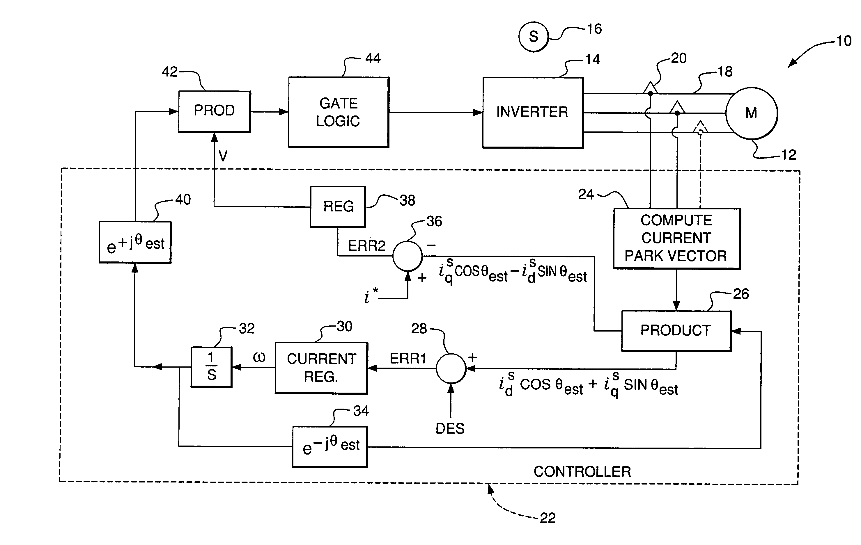
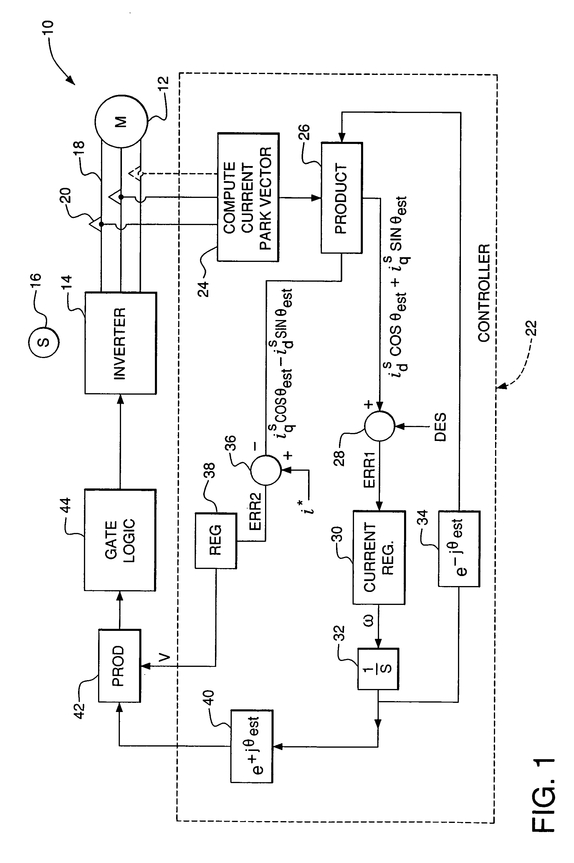
[0020]The preferred embodiments of the invention will now be described with reference to the attached drawing figures. A system and method for estimating the angular position of a current Park vector and hence controlling the electrical machine without the need for position sensors is described in U.S. Pat. No. 6,301,136, the contents of which is incorporated herein by reference in its entirety.

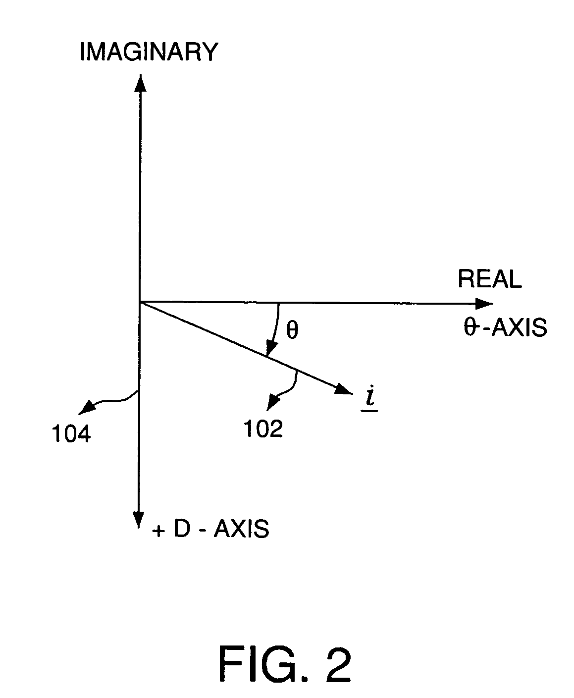
[0021]Park vectors inherently contain information on both the instantaneous magnitudes and the phase relationship of three phase rotating fields with respect to a reference coordinate system. A Park vector, in general, is a mathematical representation that describes the locus of an electrical quantity in the complex space domain (where time is a parameter). A current Park vector is defined with the vector's amplitude and the vector's direction in spatial relation to the three phases. A general discussion of Park vectors is provided in P. K. Kovacs, “Transient Phenomena in Electrical Machines,...


PUM


Abstract

A synchronous motor controller and method of controlling a synchronous motor without using rotor position sensors are provided. In a floating synchronous reference frame controller, phase currents are measured and a current Park vector is determined. The error between an initially arbitrary floating reference frame is reduced with a control loop. Decoupling terms based on the estimated speed of the rotor and the stator winding inductance are used to generate decoupled voltage terms in the v- and u-axis of the floating synchronous reference frame. The decoupled voltage command is converted back to a stator reference frame and applied to the synchronous motor via a power electronic converter. As a result u-axis current is minimized during transients, and a robust and accurate estimation of the current vector to be used in coordinate transformation for controlling the machine are achieved and the need for overrating of motor and inverter components is avoided.

Description

REFERENCE TO RELATED APPLICATIONS[0001]Related subject matter is disclosed in U.S. Pat. No. 6,301,136, issued on Oct. 9, 2001, entitled “Floating Frame Controller”, the entire contents of which is incorporated herein by reference.FIELD OF THE INVENTION[0002]The invention relates to a method and apparatus for performing electrical power conversion, and more particularly, to a position sensorless method and apparatus for controlling a power converter such as an inverter.BACKGROUND OF THE INVENTION[0003]A conventional synchronous motor typically uses rotor position sensors to provide information regarding the position of the motor's rotor with respect to the motor's stator windings. Rotor position sensors such as Hall effect devices are typically mounted in the stator, proximate the stator windings. The rotor position sensors provide rotor position information, which allows for proper control for the conversion of power that is supplied to the stator windings of an electrical machine.[...

Claims


Application Information

Patent Timeline
IPC IPC(8): H02P3/18H02P21/00
CPCH02P21/00H02P21/0046H02P21/28
Inventor SARLIOGLU, BULENTHUGGETT, COLIN E.
Owner HONEYWELL INT INC
Why Eureka
Try Eureka