Hydrophobically coated pressure sensor

Inactive Publication Date: 2005-09-13
EHNDRESS KHAUZER GMBKH KO KG
View PDF7 Cites 15 Cited by
  • Summary
  • Abstract
  • Description
  • Claims
  • Application Information

AI Technical Summary

Benefits of technology

[0008]Since water molecules of the reference air can both deposit on the rough surface and penetrate into the hair cracks, electrical connections arise between the separate islands of electrode material, so that the area of the platform electrode gets larger. The water in the hair cracks, present because of capillary condensation, likewise influences the effective electrode areas on the basis of its dielectric constant. This leads, however, to an offset of the zero-point of the pressure sensor. This effect becomes greater, the higher the relative humidity of the reference air.
[0024]The walls of the chamber are preferably kept at a temperature TK, which prevents the condensation of the molecules of the at least one coating gas and / or vapor phase and minimizes adsorption.
[0028]The build-up of the hydrophobic layer from a plurality of plies is, it is true, more complicated, but it can in some cases lead to an improved quality of the hydrophobic coating, since two or more short molecules can be bonded together for achieving a desired characteristic. Because of the lower mass of the shorter molecules, these can be evaporated more easily and exhibit a greater mobility than heavier molecules for surface diffusion processes, so that films can be formed with greater uniformity and, in some cases, even more quickly.

Problems solved by technology

For highly accurate measurements, this is not acceptable.
Especially in the case of ceramic relative pressure sensors, there is the additional difficulty in the manufacture of the sensors that the impregnation can only be done after the connecting of the separating membrane with the platform, since the temperatures occurring during the connecting are too high for the organic coating material.

Method used


Image

  • Hydrophobically coated pressure sensor
  • Hydrophobically coated pressure sensor

Examples


Embodiment Construction

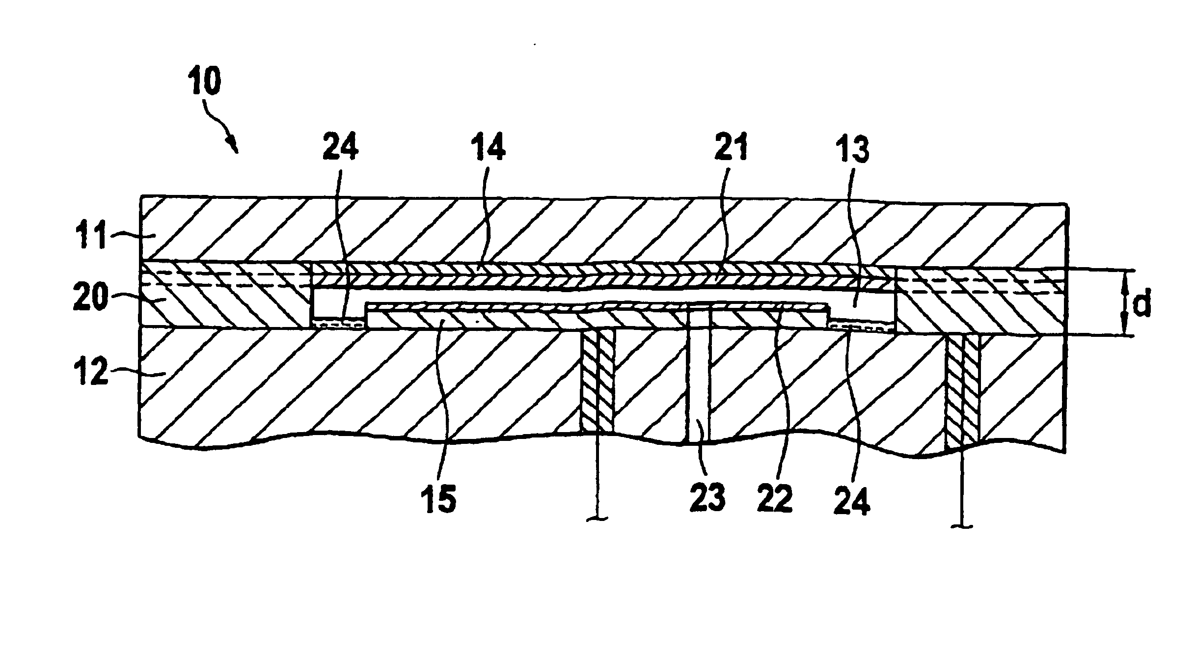
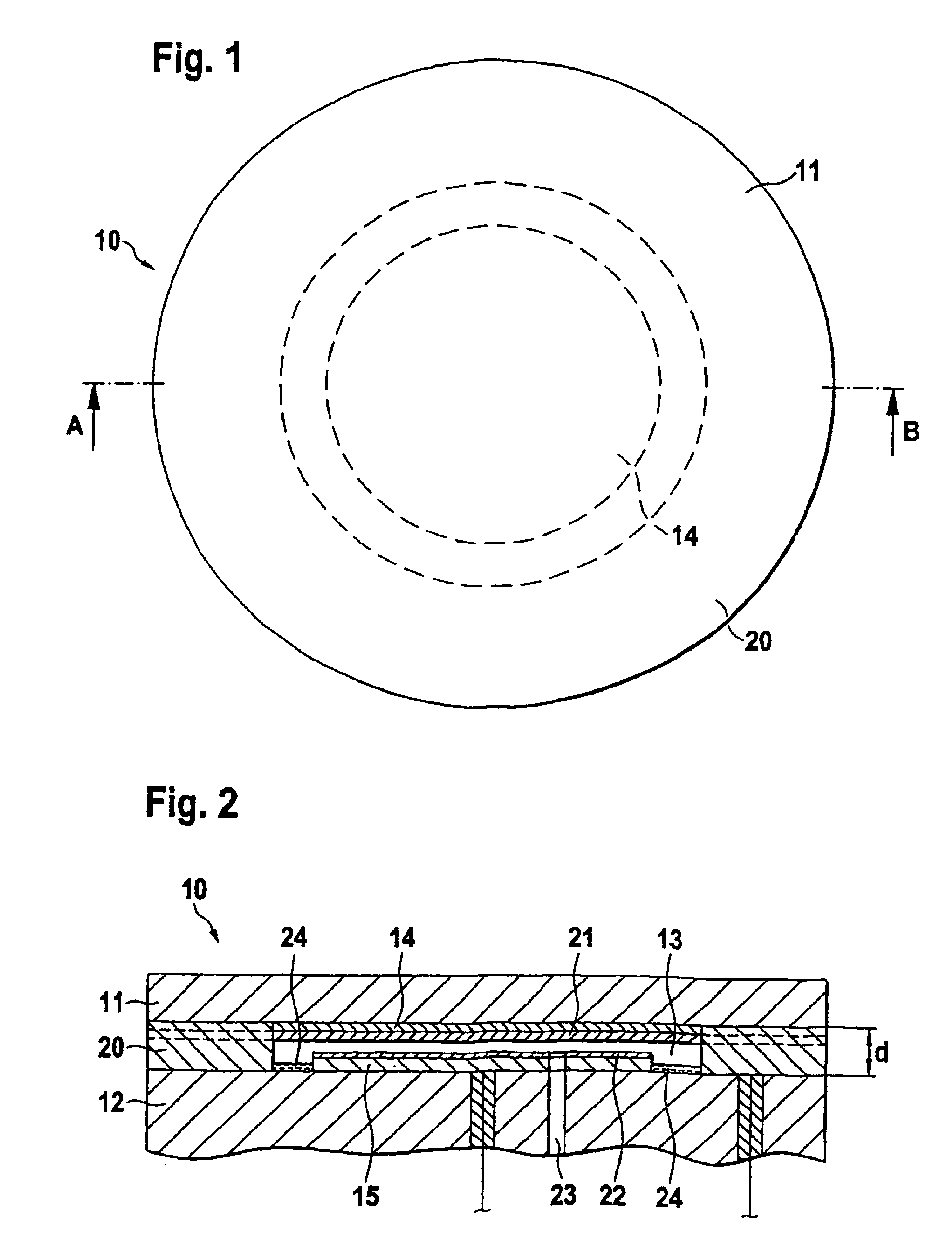
[0032]FIGS. 1 and 2 show a capacitive, ceramic pressure sensor 10. The ceramic material is e.g. the aforementioned aluminum oxide of 96 wt.-% to 99 wt.-% purity. Pressure sensor 10 has a membrane 11 in the form of a circularly round disk with plane-parallel surfaces. Additionally, the pressure sensor 10 includes a platform 12, which, except that it is thicker than the membrane 11, has the same shape.

[0033]Membrane 11 and platform 12 are, as explained above, brazed together at their respective edges along their entire circumference at a mutual separation d achieved by interposition of a spacer 20. This is done in high vacuum at a temperature of about 900° C. Because of the separation d, membrane 11 and platform 12 form a chamber 13. The membrane 11 is thin and elastic, so that it can flex under a pressure acting on it and thus move back and forth.

[0034]Electrodes 14, 15 are placed on the mutually facing surfaces of the membrane 11 and platform 12. The electrodes are preferably of tan...


PUM


Abstract

A pressure sensor for measuring a pressure includes a pressure chamber; and a deformation body, which can be exposed to a medium under pressure, and which, additionally, at least partially bounds the pressure chamber and seals such pressure-tightly from the medium; wherein the walls of the sensor chamber have a hydrophobic coating, which was applied by gas and / or vapor phase deposition. The hydrophobic coating preferably includes a silane. Especially suited are silanes having one or more hydrophobic groups R and one or more anchoring groups X. Especially preferred are: R—Si—X3, R1R2—Si—X2, R1R2R3—Si—X. The hydrophobic group R is preferably an alkyl, perfluoroalkyl, phenyl or perflurorophenyl group. The anchoring group X is preferably an —OH (silanol), —X (halide, e.g. —Cl), —OR (ester, e.g. —OCH3), —NH2 (amine), or —SH (Mercaptosilane). Additionally, aliphatic or cyclic silazanes —Si—NH—Si—, e.g. hexamethyldisilazane, can be used. Likewise suitable are compounds of the type Ry—Me—Xz, with Me=e.g. Zr, Ti.

Description

[0001]This application claims priority to German Patent Application No. PCT / EP02 / 14443, filed Dec. 18, 2002.FIELD OF THE INVENTION[0002]The present invention relates to a pressure sensor, especially a relative pressure sensor having a hydrophobic coating. Relative pressure sensors usually measure the difference between the pressure in a medium being measured and the current ambient atmospheric pressure. A relative pressure sensor includes, in general, a platform on which a measuring membrane, or diaphragm, is attached pressure-tightly at its edge, with a pressure chamber being formed between the measuring membrane and the platform. For relative pressure measurement, reference air is introduced into the pressure chamber through an opening in the platform, and the measuring membrane surface facing away from the measuring chamber is exposed to the pressure being measured. The resulting deformation of the measuring membrane is a measure of the relative pressure, and this is transduced i...

Claims


Application Information

Patent Timeline
IPC IPC(8): G01L7/00G01L9/12G01L9/00G01L19/06
CPCG01L9/0075
Inventor HEGNER, FRANKDREWES, ULFERTROSSBERG, ANDREASSCHMIDT, ELKE
Owner EHNDRESS KHAUZER GMBKH KO KG
Why Eureka
Try Eureka