Flexible stent

Inactive Publication Date: 2005-09-13
CARDINAL HEALTH SWITZERLAND 515 GMBH
View PDF135 Cites 75 Cited by
  • Summary
  • Abstract
  • Description
  • Claims
  • Application Information

AI Technical Summary

Benefits of technology

[0024]This process can be used to locally change the geometry of the cylindrical metallic tube. An advantage seen by this process is the ability to manufacture a tapered strut along the stent. Further, struts of

Problems solved by technology

Although a number of stent designs have been reported, these designs have suffered from a number of limitations.
This design has at least one important disadvantage, for example, according to this design, protruding edges occur when the stent is flex

Method used


Image

  • Flexible stent
  • Flexible stent
  • Flexible stent

Examples


Example

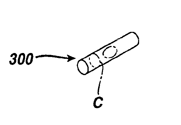
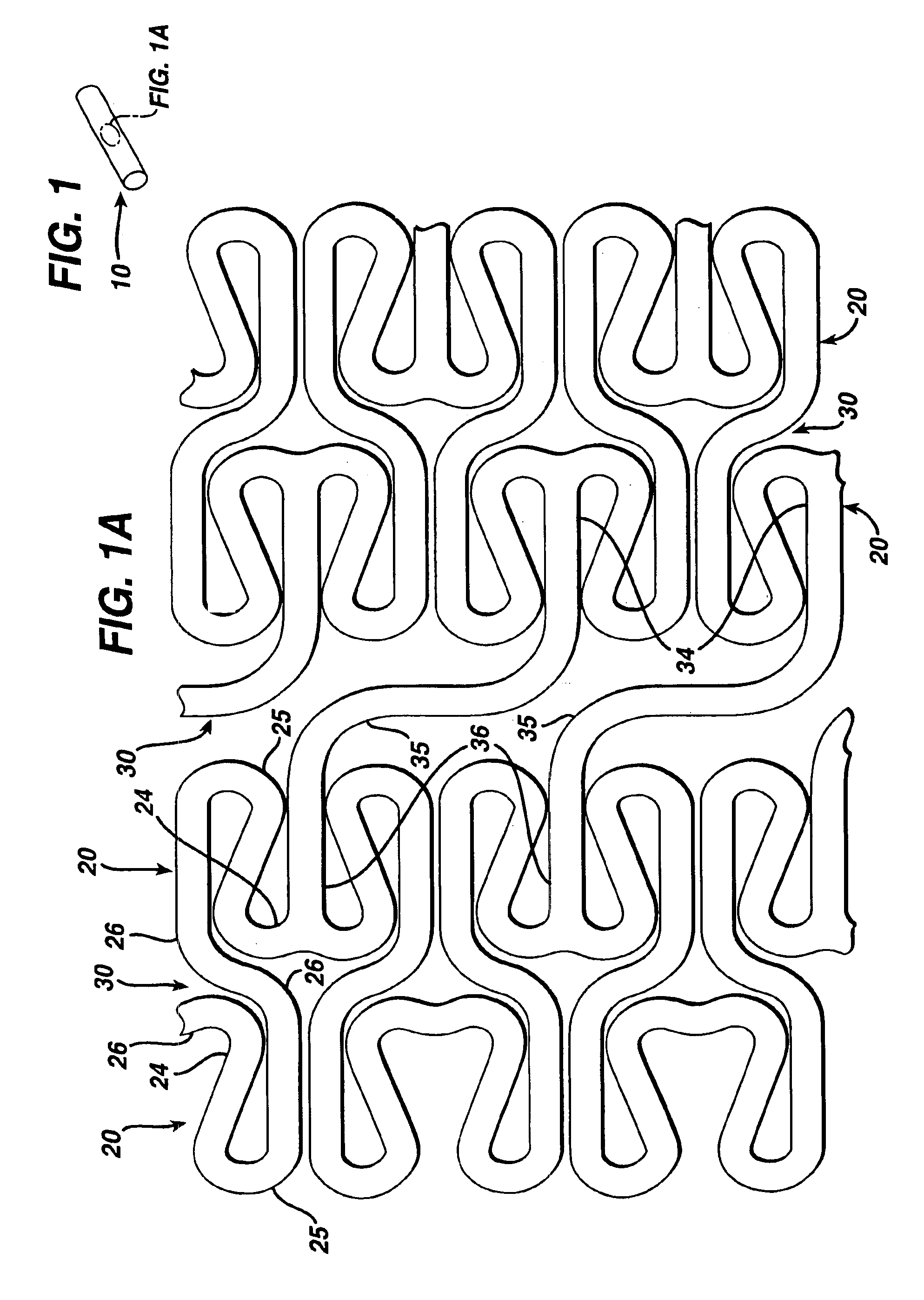
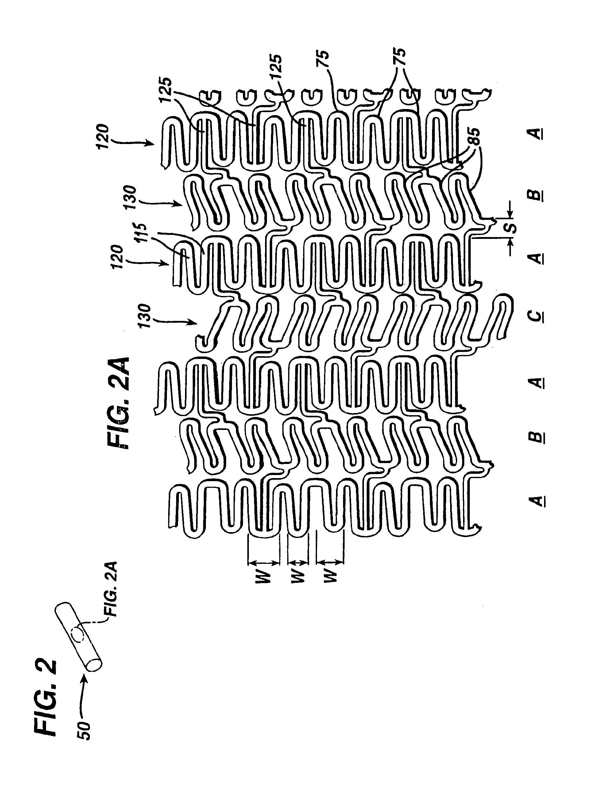
[0034]As can be seen in FIG. 1, there is described a cylindrical stent 10 which has a series of folded strut sections 20 connected by a series of flexible sections 30. The folded strut sections 20 comprise a generally folded strut member 25 having a pair of ends 24, 26. Each of the pair of ends 24, 26 is connected to another folded strut member 25 and also to the end of a flexible member 35. Thus, each end 34, 36 of a flexible member 35 is connected to two ends 24, 26 of a folded strut 25 section member.

[0035]Each of the folded struts 25 takes on a generally irregular pattern. On the other hand, each of the flexible sections 35 takes on a generally undulating pattern. The folded strut sections 20 wrap circumferentially around the cylindrical shape of the stent 10. Each flexible section 30 also connects to a folded strut section 20 around the circumference of the stent. It will be noticed that each adjacent flexible section 30 is positioned 180° out of phase with each other.

[0036]The...


PUM


Abstract

A preferred embodiment of a stent provides a folded strut section that provides both structural rigidity and reduction in foreshortening of the stent mechanism. A flexible section provides flexibility for delivery of the stent mechanism. In a second embodiment, flexible section columns are angled with respect to each other, and to the longitudinal axis of the stent. These relatively flexible sections are oppositely phased in order to negate any torsion along their length. In yet another embodiment, the flexible connector can take on an undulating shape (like an “N”), but such that the longitudinal axis of the connector is not parallel with the longitudinal axis of the stent. Finally, a new method is disclosed for making stents. The method consists of performing a standard photochemical machining process of cutting, cleaning and coating the tube with a photoresist. However, unlike former methods, the photoresist image is developed on the surface of the cylindrical metallic tube, which results in a controlled variable etching rate at selected sites on the cylindrical metallic tube during the etching process. Further embodiments provide living hinge connectors and connections along the length of the radial strut member.

Description

RELATED APPLICATIONS[0001]This application claims priority to provisional application number 60 / 272,696, filed Mar. 1, 2001.BACKGROUND ART[0002]A stent is commonly used as a tubular structure left inside the lumen of a duct to relieve an obstruction. Commonly, stents are inserted into the lumen in a non-expanded form and are then expanded autonomously (or with the aid of a second device) in situ. A typical method of expansion occurs through the use of a catheter mounted angioplasty balloon, which is inflated within the stenosed vessel or body passageway, in order to shear and disrupt the obstructions associated with the wall components of the vessel and to obtain an enlarged lumen.[0003]In the absence of a stent, restenosis may occur as a result of elastic recoil of the stenotic lesion. Although a number of stent designs have been reported, these designs have suffered from a number of limitations. These include restrictions on the dimension of the stent.[0004]Other stents are descri...

Claims


Application Information

Patent Timeline
IPC IPC(8): A61F2/06A61F2/90
CPCA61F2/91A61F2/915A61F2002/91508A61F2002/91516A61F2002/91525A61F2002/91533A61F2002/91558A61F2002/91566A61F2002/91575A61F2230/0054
Inventor MAJERCAK, DAVID C.
Owner CARDINAL HEALTH SWITZERLAND 515 GMBH
Why Eureka
Try Eureka