Wrapping films with mating cling strips

a technology of cling strips and wrapping films, which is applied in the field of improving the cling film system, can solve the problems of cling films that are relatively complex and expensive to manufacture, and can not be easily re-used,

Inactive Publication Date: 2005-09-13
ILLINOIS TOOL WORKS INC
View PDF19 Cites 32 Cited by
  • Summary
  • Abstract
  • Description
  • Claims
  • Application Information

AI Technical Summary

Benefits of technology

[0013]With the foregoing in mind, it is a feature and advantage of the invention to provide an improved cling film system which provides improved cling properties as well as corrosion resistance, is relatively inexpensive to manufacture, and provides improved toughness and puncture resistance.
to provide an improved cling film system which provides improved cling properties as well as corrosion resistance, is relatively inexpensive to manufacture, and provides improved toughness and puncture resistance.

Problems solved by technology

These cling films are relatively complex and expensive to manufacture.
Another difficulty encountered with prior cling films (both single layer and multi-layer) is that they may puncture and tear when exposed to the sharp edges of steel coils or other articles being wrapped.

Method used


Image

  • Wrapping films with mating cling strips
  • Wrapping films with mating cling strips
  • Wrapping films with mating cling strips

Examples


Embodiment Construction

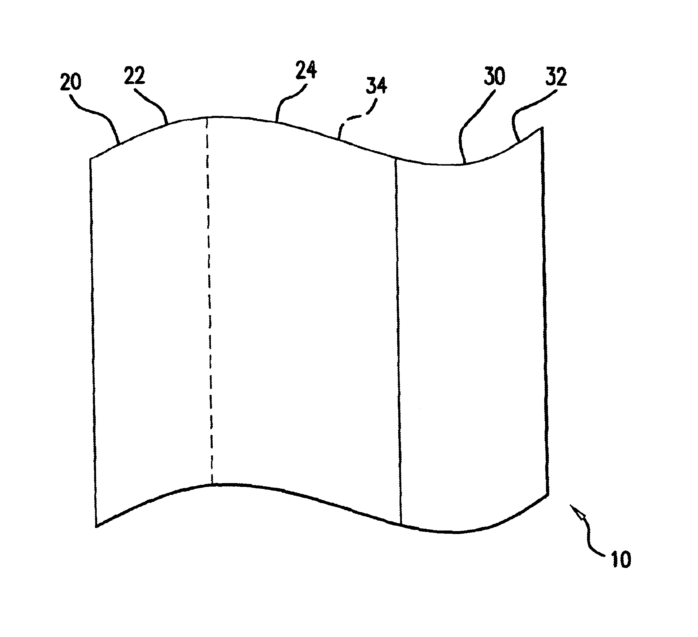
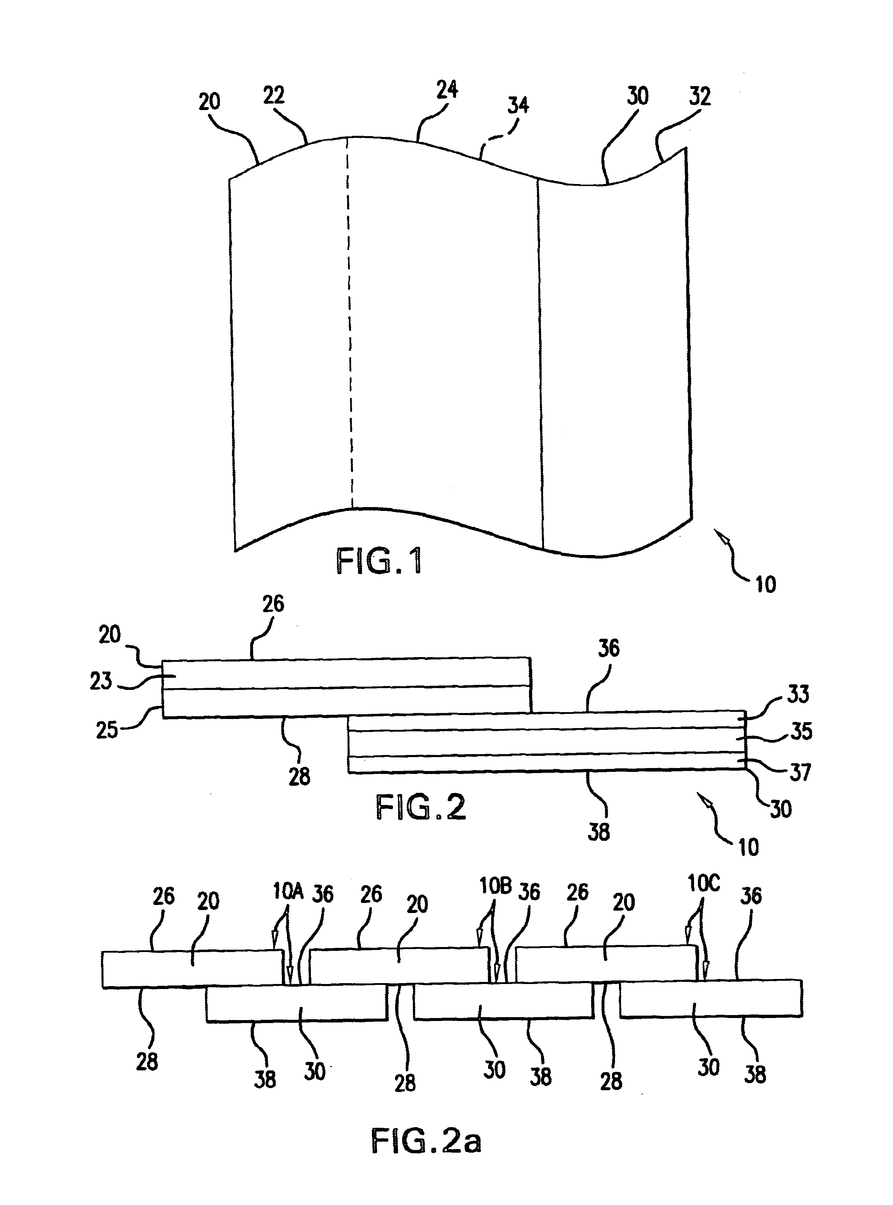
[0019]Referring to FIG. 1, a cling film system 10 of the invention includes a first ply 20 and a second ply 30. The first ply 20 includes a non-overlapping portion 22 and an overlapping portion 24 which overlaps with the second ply. The second ply 30 includes a non-overlapping portion 32 and an overlapping portion 34 which overlaps with the first ply. For purposes of this invention, the term “ply” refers to a separately formed film. The first and second plies 20 and 30 may be formed using separate extrusion lines, or may be formed at different times using the same extrusion line, or may be formed simultaneously on the same extrusion line at different positions on the bubble or web. The extrusion line(s) may be blown film, cast film, or one of each.

[0020]The overlapping portions 24 and 34 represent the area over which the first ply 20 and the second ply 30 are joined and cling together. The overlapping portions 24 and 34 should have a width of about 2-86 inches, suitably about 5-27 i...


PUM

PropertyMeasurementUnit
widthaaaaaaaaaa
widthaaaaaaaaaa
widthaaaaaaaaaa

Abstract

A cling film system includes first and second film piles having different composition. Each film ply includes at least one cling layer and, desirably, one or more additional layers. Each film ply includes an overlapping portion and a second portion. The cling layer of the first film ply engages the cling layer of the second film ply in the overlapping portion of the first film ply and in the overlapping portion of the second film ply.

Description

FIELD OF THE INVENTION[0001]This invention is directed to an improved cling film system, useful for wrapping steel coils and other articles in a spiral fashion.BACKGROUND OF THE INVENTION[0002]Various single layer and multiple layer cling films have been used for wrapping steel coils and other articles. Cling films are typically based on polyethylene homopolymers or copolymers including, without limitation, low density polyethylene, linear low density polyethylene, ethylene vinyl acetate and the like. In addition to the polymer components, these films typically include a balance of additives which are intended to improve cling, and additives employed for other purposes which may have an undesirable anti-cling effect.[0003]A cling film must have the ability to stick or cling to itself, or to other films having the same composition. One conventional cling film is based on linear low density polyethylene modified with a cling additive, such as polyisobutylene, a volatile corrosion inhi...

Claims


Application Information

Patent Timeline
Patent Type & Authority Patents(United States)
IPC IPC(8): B32B27/08
CPCB32B27/08Y10T428/1393Y10T428/1352Y10T428/19Y10T428/2878Y10T428/1369Y10T428/24992Y10T428/24752B32B27/18B32B27/306B32B27/32B32B2272/00B32B2323/043B32B2323/046B32B2331/04Y10T428/249922Y10T428/31913
Inventor SHIRRELL, JACK N.RIGNEY, PATRICK T.PRESNELL, ELDRIGE J.KELLERMANN, JEFFREY G.BRUNNING, CHRISTOPHERMAKA, XAVIER J.ROSENTHAL, GUY L.BROUSSARD, CHAD D.
Owner ILLINOIS TOOL WORKS INC
Why Eureka
Try Eureka