Thermal barrier coatings, components, method and apparatus for determining past-service conditions and remaining life thereof

a technology of thermal barrier coating and past-service condition, which is applied in the direction of luminescent dosimeters, optical radiation measurement, fluorescence/phosphorescence, etc., can solve the problems of component failure, coating sputtering, and inability to meet the requirements of the component,

Inactive Publication Date: 2005-09-13
GENERAL ELECTRIC CO
View PDF16 Cites 35 Cited by
  • Summary
  • Abstract
  • Description
  • Claims
  • Application Information

AI Technical Summary

Benefits of technology

[0015]The present invention also provides an apparatus for determining at least one of past-service conditions and remaining useful life of at least one of a component of a combustion engine and a thermal barrier coating thereof, which component is used in the hot-gas path of the combustion engine. The apparatus comprises (1) a source of radiation having a first wavelength range directed at the thermal barrier coating that comprises at least one PL material capable of emitting radiation having a second w

Problems solved by technology

Despite great care taken during manufacture to ensure good adhesion of the thermal barrier coating to the underlying material of the turbine component, thermal cycling during use of such a component eventually leads to spalling of the coating.
In addition, erosion of the thermal barrier coating is inevitable over an extended period of use.
Such a spalling or erosion would eventually expose the underlying alloy to extreme temperatures that would lead to failure of the component.
Such an inspection often requires taking the engine component out of service and is time-consuming.
While that method determines when a spall has occurred, it is unable to determine either the degree of deterioration in an intact coating.
However, traditional methods of inspection, such

Method used


Image

  • Thermal barrier coatings, components, method and apparatus for determining past-service conditions and remaining life thereof
  • Thermal barrier coatings, components, method and apparatus for determining past-service conditions and remaining life thereof
  • Thermal barrier coatings, components, method and apparatus for determining past-service conditions and remaining life thereof

Examples


Embodiment Construction

[0024]As used herein, the term “combustion engine” means any engine that generates work using energy derived from combustion of a fuel. A combustion engine can include components or assemblies of components that convert the energy of the combustion to other forms of energy. Thus, the term “combustion engine” includes turbine engines.

[0025]As used herein, the term “elevated temperatures” means temperatures greater than about 700° C.

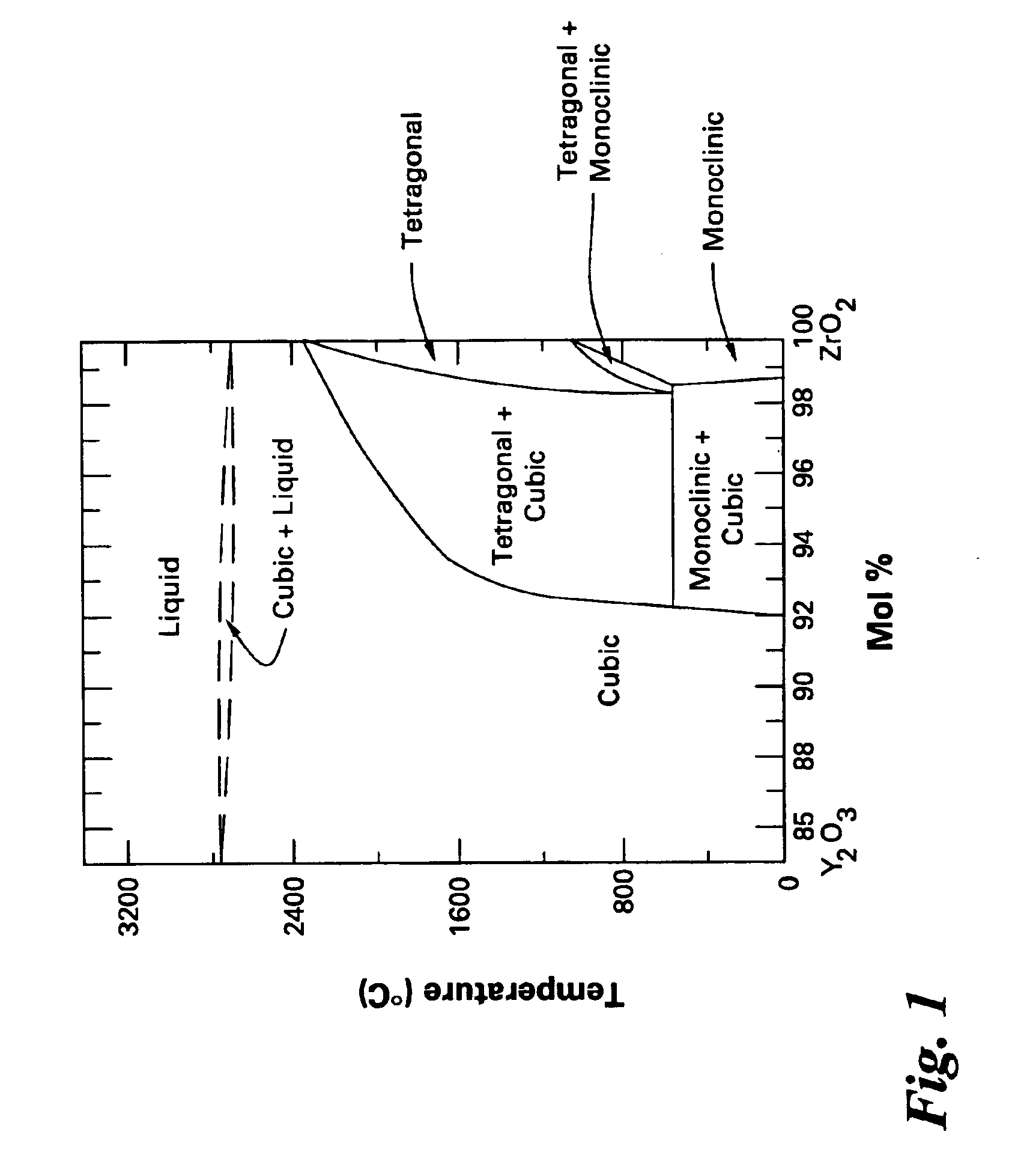
[0026]Yttria-stabilized zirconia is a material commonly used as thermal barrier coating (“TBC”) for components used in the hot-gas path of gas-turbine engines. This material has many advantages such as high tolerances for thermal shock, low thermal conductivity, and a higher melting point than most oxides. However, one of the limitations of pure zirconia is that it undergoes phase transitions as temperature changes. At temperatures less than 1170° C., the equilibrium phase of zirconia is monoclinic. Between 1170° C. and 2370° C. it is tetragonal, and above...


PUM

PropertyMeasurementUnit
Percent by massaaaaaaaaaa
Nanoscale particle sizeaaaaaaaaaa

Abstract

A method for determining past-service conditions and/or remaining useful life of a component of a combustion engine and/or a thermal barrier coating (“TBC”) of the component comprises providing a photoluminescent (“PL”) material in the TBC, directing an exciting radiation at the TBC, measuring the intensity of a characteristic peak in the emission spectrum of the PL material, and correlating the intensity of the characteristic peak or another quantity derived therefrom to an amount of a new phase that has been formed as a result of the exposure of the component to extreme temperatures. An apparatus for carrying out the method comprises a radiation source that provides the exciting radiation to the TBC, a radiation detector for detecting radiation emitted by the PL material, and means for relating a characteristic of the emission spectrum of the PL material to the amount of the new phase in the TBC, thereby inferring the past-service conditions or the remaining useful life of the component.

Description

[0001]This is a Divisional of U.S. Ser. No. 09 / 683,385 filed Dec. 20, 2001, now U.S. Pat. No. 6,730,918.[0002]This invention was first conceived or reduced to practice in the performance of work under contract DE-FC26-01NT41021 awarded by the United States Department of Energy. The United States of America may have certain rights to this invention.BACKGROUND OF THE INVENTION[0003]The present invention relates to thermal barrier coatings, a method, and an apparatus for determination of past-service conditions of coatings and parts and remaining life thereof. In particular, the present invention relates to such a method and an apparatus by a non-destructive optical determination of a particular crystalline phase in a thermal barrier coating.[0004]The constant demand for increased operating temperature in gas turbine engines has necessitated the development of ceramic coating materials that can insulate the turbine components such as turbine blades and vanes from the heat contained in ...

Claims


Application Information

Patent Timeline
IPC IPC(8): G01N21/64
CPCG01N21/6489G01N21/8422
Inventor SRIVASTAVA, ALOK MANISETLUR, ANANT ACHYUTCOMANZO, HOLLY ANNDEVITT, JOHN WILLIAMRUUD, JAMES ANTHONYBREWER, LUKE NATHANIEL
Owner GENERAL ELECTRIC CO
Why Eureka
Try Eureka