MEMS based over-the-air optical data transmission system

Inactive Publication Date: 2005-09-13
MARGALIT SHLOMO +1
View PDF6 Cites 23 Cited by
  • Summary
  • Abstract
  • Description
  • Claims
  • Application Information

AI Technical Summary

Benefits of technology

[0016]Another feature of the present invention is the use of optical fiber to carry light from a light source in data equipment to the optical beam transmitter positioned on the roof or in a window. Another optical fiber carries the light from an optical beam receiver on the roof or in a window to a detector in the data equipment. This facilitates the changing of data equipment, changing data rates, changing protocols, etc., without the need to replace the optical beam transmitter or beam receiver. The system may be upgraded to carry light in more then one wavelength using the same optical beam transmitter and receiver. For long transmission lengths, an optical fiber amplifier could be installed between the light source and the optical beam transmitter, or between the optical beam receiver and the detector, or both locations. For systems located in areas with common fog problems, such amplifiers could be

Problems solved by technology

An optical interconnect with light beams between buildings suffers from a difficulty associated with the movement of the buildings.
Sin

Method used


Image

  • MEMS based over-the-air optical data transmission system
  • MEMS based over-the-air optical data transmission system
  • MEMS based over-the-air optical data transmission system

Examples


Embodiment Construction

[0034]The invention comprises a method and apparatus for a MEMS based over-the-air optical data transmission system. In the following description, numerous specific details are set forth to provide a more thorough description of embodiments of the invention, It will be apparent, however, to one skilled in the art, that the invention may be practiced without these specific details. In other instances, well known features have not been described in detail so as not to obscure the invention.

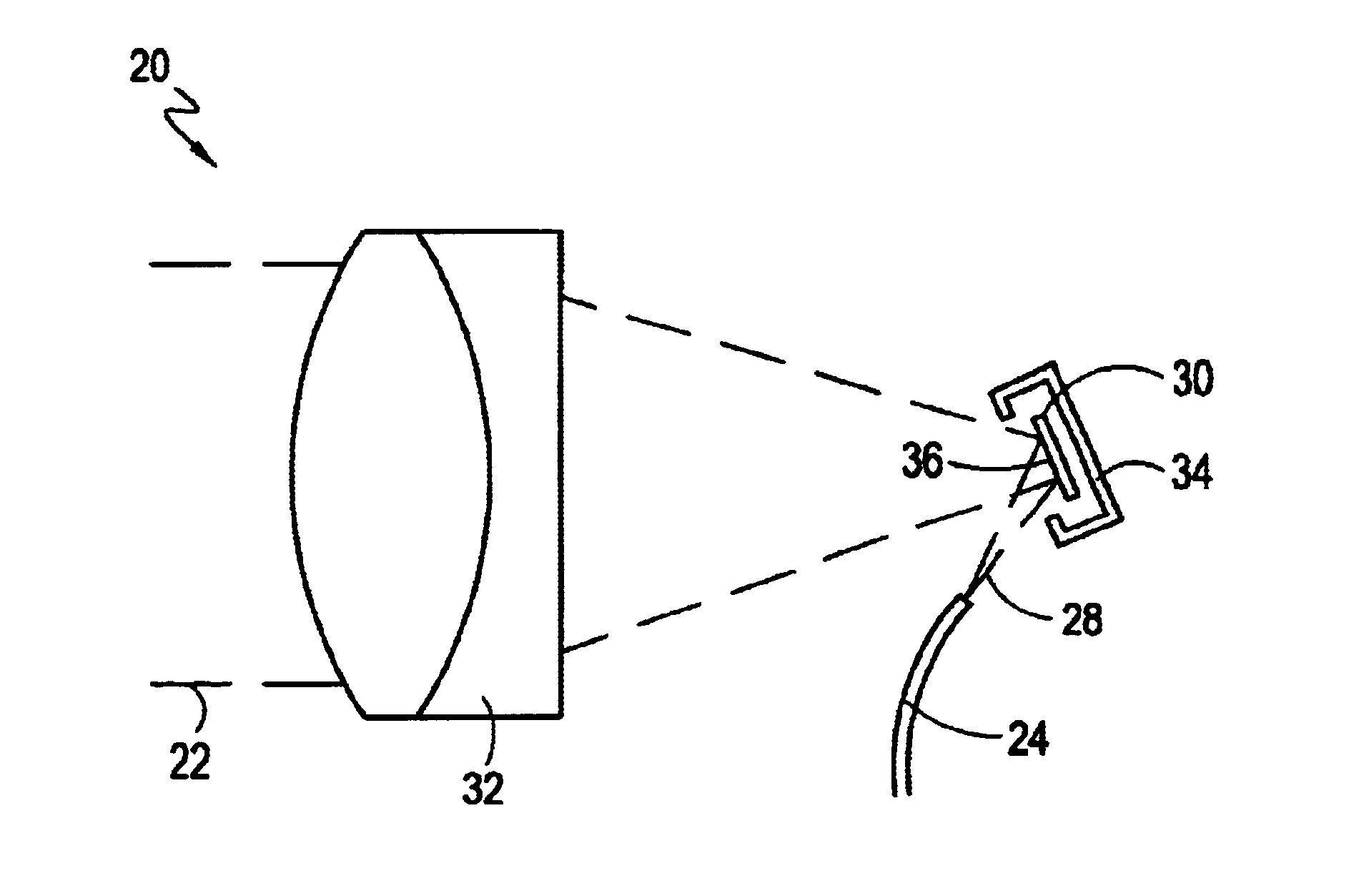
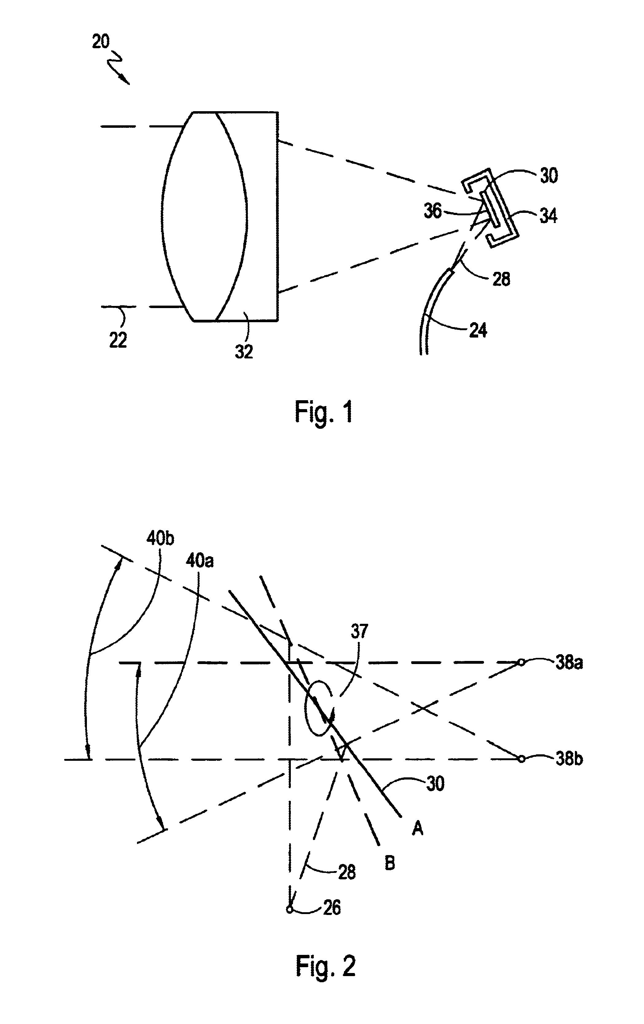
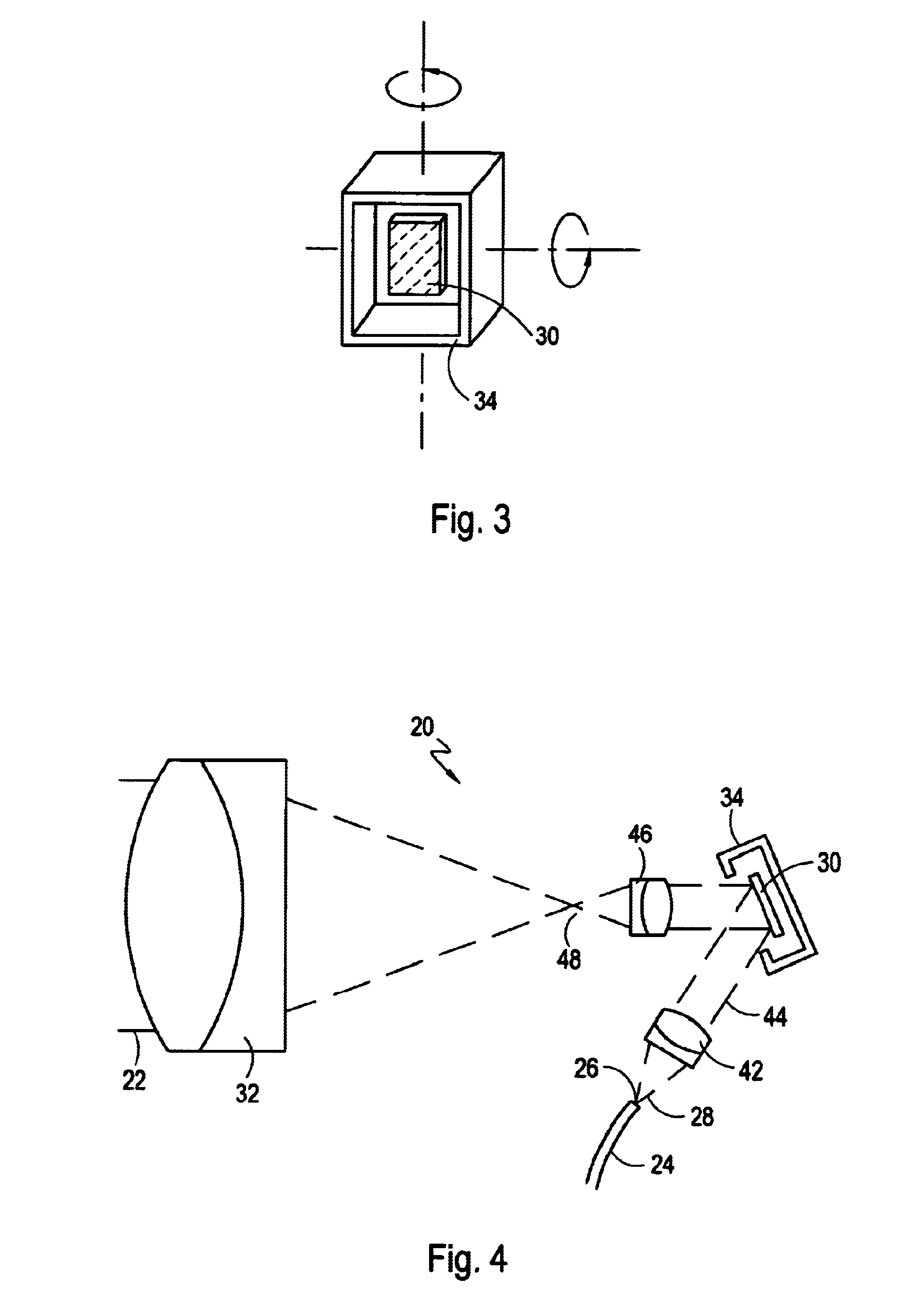
[0035]FIG. 1 shows the construction of a beam transceiver 20 in accordance with one embodiment of the invention. The beam transceiver 20 may operate as a beam transmitter or as a beam receiver, or as both. In the beam transceiver 20 shown in FIG. 1, a light beam 22 that propagates in the optical fiber 24 exists in the fiber end 28 in a cone 28. The optical fiber 24 is a common single-mode telecommunications fiber, with a core diameter of approximately 10 microns and a cladding diameter of 125 micron...


PUM


Abstract

Building-to-building over the air transmission of optical data is a growing area of data communications. The fast growing use of bandwidth mandates the use of over the air transmission equipment capable of similar performance as the performance of fiber optic transmission, for distances of 3-10 Km. Transparent transmission is important to enable seamless growth from low data-rare to Gbps rates, and then to Dense Wavelength Division Multiplexed (DWDM) transmission of several wavelengths. The only way to achieve the required performance is with narrow, directable beams. This patent application discloses a Micro-Electro-Mechanical-Systems (MEMS) mirror based, over the air, optical data transmission system. A narrow optical beam is used and a MEMS mirror fine-tunes the aiming of the beam to track building movement, vibrations etc.

Description

[0001]This non-provisional application takes priority from U.S. Provisional Application Ser. No. 60 / 210,613 filed on Jun. 9, 2000.BACKGROUND OF THE INVENTION[0002]A description of some technologies related to embodiments of the invention follows:[0003]U.S. Pat. No. 4,662,004 Fredriksen, et al. Fredriksen describes an optical communication link that includes a separate laser (in addition to the data transmission laser), which returns information about the level of the received signal to the transmitter. This separate laser is adjusted to emit power proportional to the received beam power.[0004]U.S. Pat. No. 4,832,402 Brooks. Brooks describes a fast scanning mirror used to time-multiplex light beam into several steering mirrors, in which each of the steering mirrors aim the beam into one or a group of targets clustered together. The steering mirrors are slow due to the large angle required. Brooks also describes the use of “beacon transmitters” to said in target tracking (column 9 lin...

Claims


Application Information

Patent Timeline
IPC IPC(8): G02B26/08H04B10/10
CPCG02B26/0841H04B10/1127
Inventor MARGALIT, SHLOMOLAOR, HERZEL
Owner MARGALIT SHLOMO
Why Eureka
Try Eureka