Finned carbine handguard assembly

a technology for carbines and handguards, which is applied in the field of finned carbine handguard assemblies, can solve the problems that conventional commercial plastic handguards without aluminum heat shields were rendered useless after the same testing, and achieve the effects of high melting point, good impact resistance, and high strength

Active Publication Date: 2005-09-20
JJE BRANDS LLC
View PDF20 Cites 38 Cited by
  • Summary
  • Abstract
  • Description
  • Claims
  • Application Information

AI Technical Summary

Benefits of technology

[0004]The preferred material is a glass fiber reinforced polyamide (thermoplastic) with good impact resistance, high strength, and a high melting point (590° F. minimum). Additives are to be used for increased heat stabilization, heat aging resistance, an

Problems solved by technology

In comparison, conventional commercial plastic handguards without

Method used


Image

  • Finned carbine handguard assembly
  • Finned carbine handguard assembly
  • Finned carbine handguard assembly

Examples


Embodiment Construction

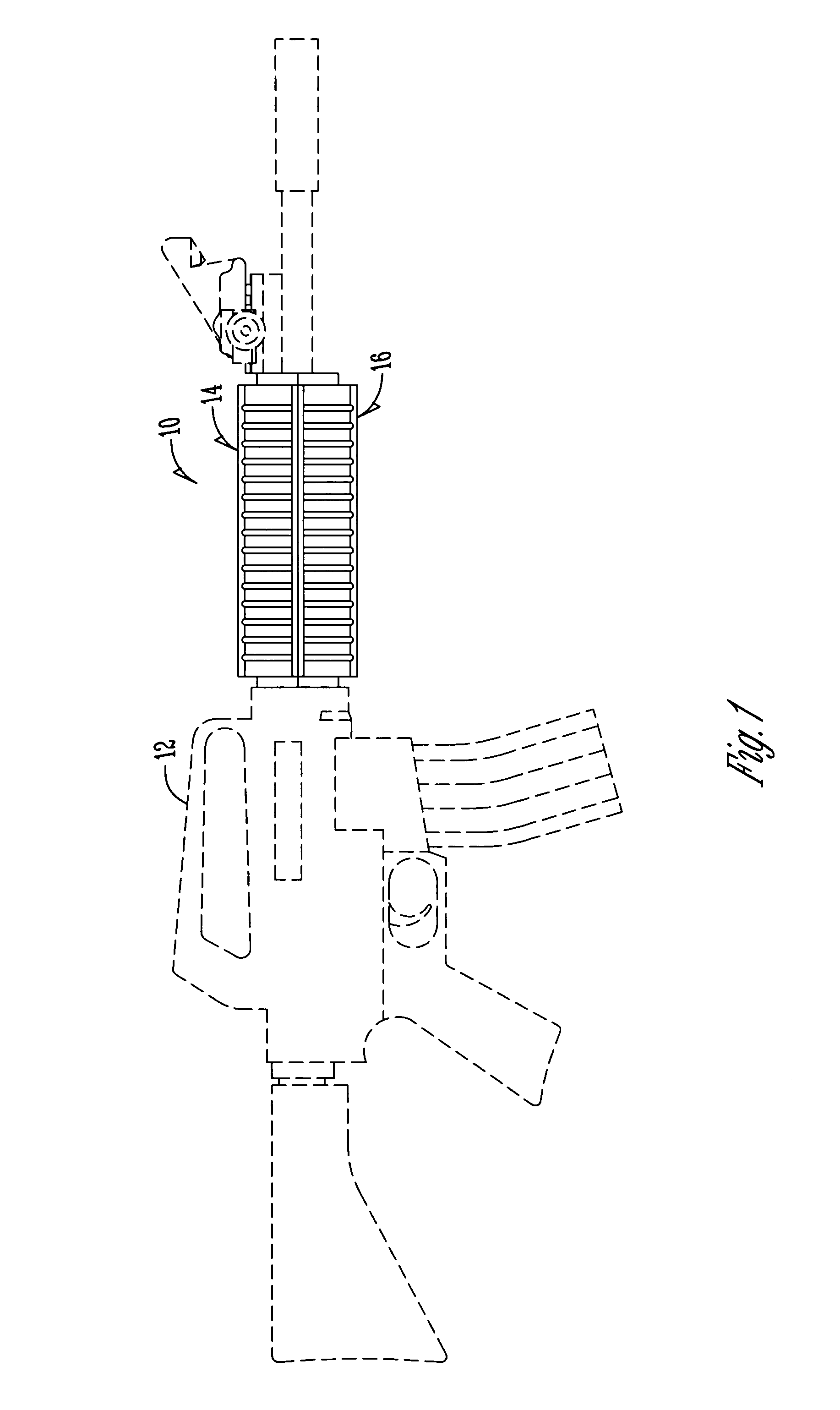
[0014]The handguard of this invention is referred to generally in FIG. 1 by the reference numeral 10 and is shown mounted on an M-16 rifle 12.

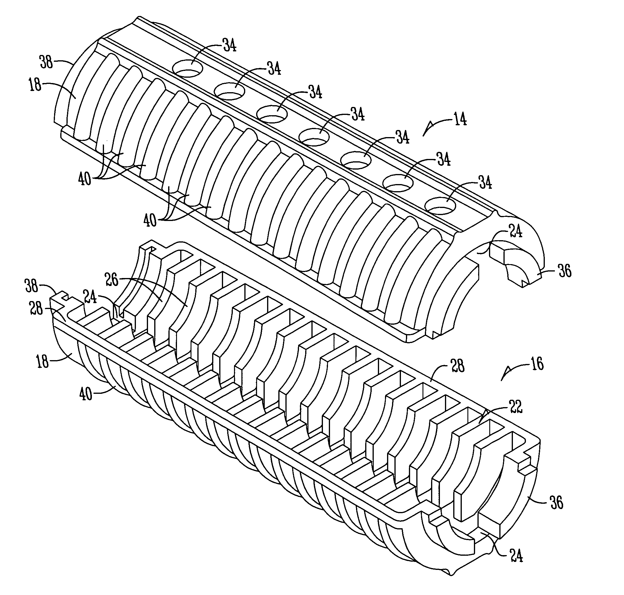
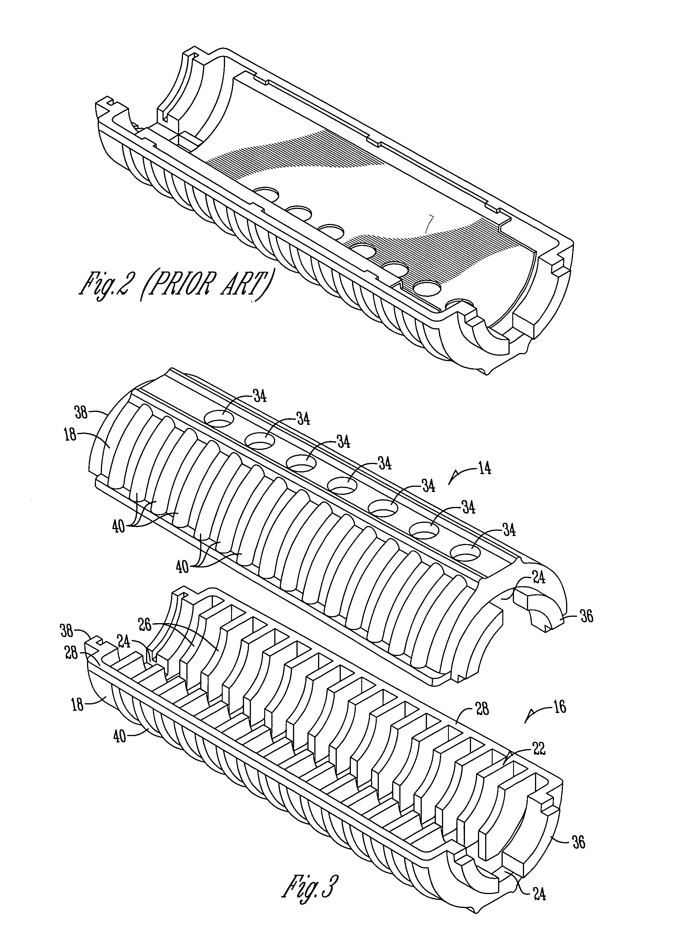
[0015]The handguard 10 includes upper and lower half sections 14 and 16. Each of the half sections include a semi-cylindrical or oval shaped outer wall 18 having an inner surface 32 on which is mounted a plurality of coplaner fin portions 22. The fin portions are spaced apart along their inner free ends to form a channel 24 for a gas tube (not shown).

[0016]Each of the fin portions include an inner concave edge 26 having at its opposite ends straight edges 28 and 30 which extend to the inner surface 32 of the wall 18. The concave edges 26 when mounted on the barrel of a gun will be in spaced relationship thereto to avoid interfering with the operation of the weapon but close enough to absorb heat produced during the firing of the gun.

[0017]A series of air circulation holes 34 are provided between the fin portions 22 in the channel wall 18.

[0018...


PUM


Abstract

A gun barrel handguard includes half sections having longitudinally spaced apart fins of plastic material positioned around the exterior of the gun barrel for absorbing heat but preventing it from being quickly transmitted to the exterior of the handguard.

Description

BACKGROUND OF THE INVENTION[0001]Rapid firing of a rifle produces substantial heat which must be dissipated in a controlled manner to prevent damage to the weapon and injury to the hand of the person holding the gun. Representative of current hand guards is the handguard shown in FIG. 2 which includes a plastic outer shell with an internal metallic liner spaced from the barrel of the gun to absorb the heat produced.[0002]What is needed is a handguard which will absorb more heat faster and yet protect the user's hands.BRIEF SUMMARY OF THE INVENTION[0003]The handguard of this invention utilizes no metallic liner but instead provides hand guard half sections made entirely of plastic material with radially extending fins on the inner side wall that function to absorb the heat generated by the gun barrel.[0004]The preferred material is a glass fiber reinforced polyamide (thermoplastic) with good impact resistance, high strength, and a high melting point (590° F. minimum). Additives are t...

Claims


Application Information

Patent Timeline
IPC IPC(8): F41A13/12F41A13/00F41C23/16
CPCF41A13/12F41C23/16
Inventor LUTH, RANDY E.
Owner JJE BRANDS LLC
Why Eureka
Try Eureka