Ammonia removal from fly ash

a technology of fly ash and ammonia, which is applied in the field of coal ash treatment, can solve the problems of limiting the use of cost sensitive installations of fly ash, ash that has been treated to reduce nox, and contaminated by unburned carbon or ammonia compounds, and achieves the effect of effective and efficien

Inactive Publication Date: 2005-09-20
WISCONSIN ELECTRIC POWER
View PDF12 Cites 10 Cited by
  • Summary
  • Abstract
  • Description
  • Claims
  • Application Information

AI Technical Summary

Benefits of technology

[0017]It is therefore an advantage of the present invention to provide an effective and efficient system and apparatus for removing ammonia compounds and other contaminants from fly ash.

Problems solved by technology

However, ash that has been treated to reduce NOx and which is contaminated either by unburned carbon or ammonia compounds is not marketable.
While these systems may be suitable for certain installations, they do have efficiency problems, such as excessive heat loss, that may limit their use in cost sensitive installations.

Method used


Image

  • Ammonia removal from fly ash
  • Ammonia removal from fly ash
  • Ammonia removal from fly ash

Examples


example 1

[0035]A sample of ASTM C-618 Class C fly ash containing ammonia was obtained from a coal fired steam generator. The sample of fly ash was measured for ammonia levels and it was determined that the ammonia levels were 51 mg. / kg. The sample of fly ash was also measured for loss on ignition (carbon) levels and it was determined that the loss on ignition (carbon) levels were 0.4%. The sample of fly ash was then continuously heated at 1000° F. (538° C.) until a constant mass was attained and thus no loss on ignition (carbon) remained in the fly ash. The heated sample of fly ash was then measured for ammonia levels and it was determined that the ammonia levels were less than 2 mg. / kg. This test confirmed that both ammonia and loss on ignition (carbon) were removed from the sample of ASTM C-618 Class C fly ash containing ammonia when heated at 1000° F. (538° C.).

example 2

[0036]A sample of ASTM C-618 Class F fly ash containing ammonia was obtained from another coal fired steam generator. The sample of fly ash was measured for ammonia levels and it was determined that the ammonia levels were 170 mg. / kg. The sample of fly ash was also measured for loss on ignition (carbon) levels and it was determined that the loss on ignition (carbon) levels were 2.9%. The sample of fly ash was then continuously heated at 1000° F. (538° C.) until a constant mass was attained and thus no loss on ignition (carbon) remained in the fly ash. The heated sample of fly ash was then measured for ammonia levels and it was determined that the ammonia levels were less than 2 mg. / kg. This test confirmed that both ammonia and loss on ignition (carbon) were removed from the sample of ASTM C-618 Class F fly ash containing ammonia when heated at 1000° F. (538° C.).


PUM

PropertyMeasurementUnit
temperatureaaaaaaaaaa
specific gravityaaaaaaaaaa

Abstract

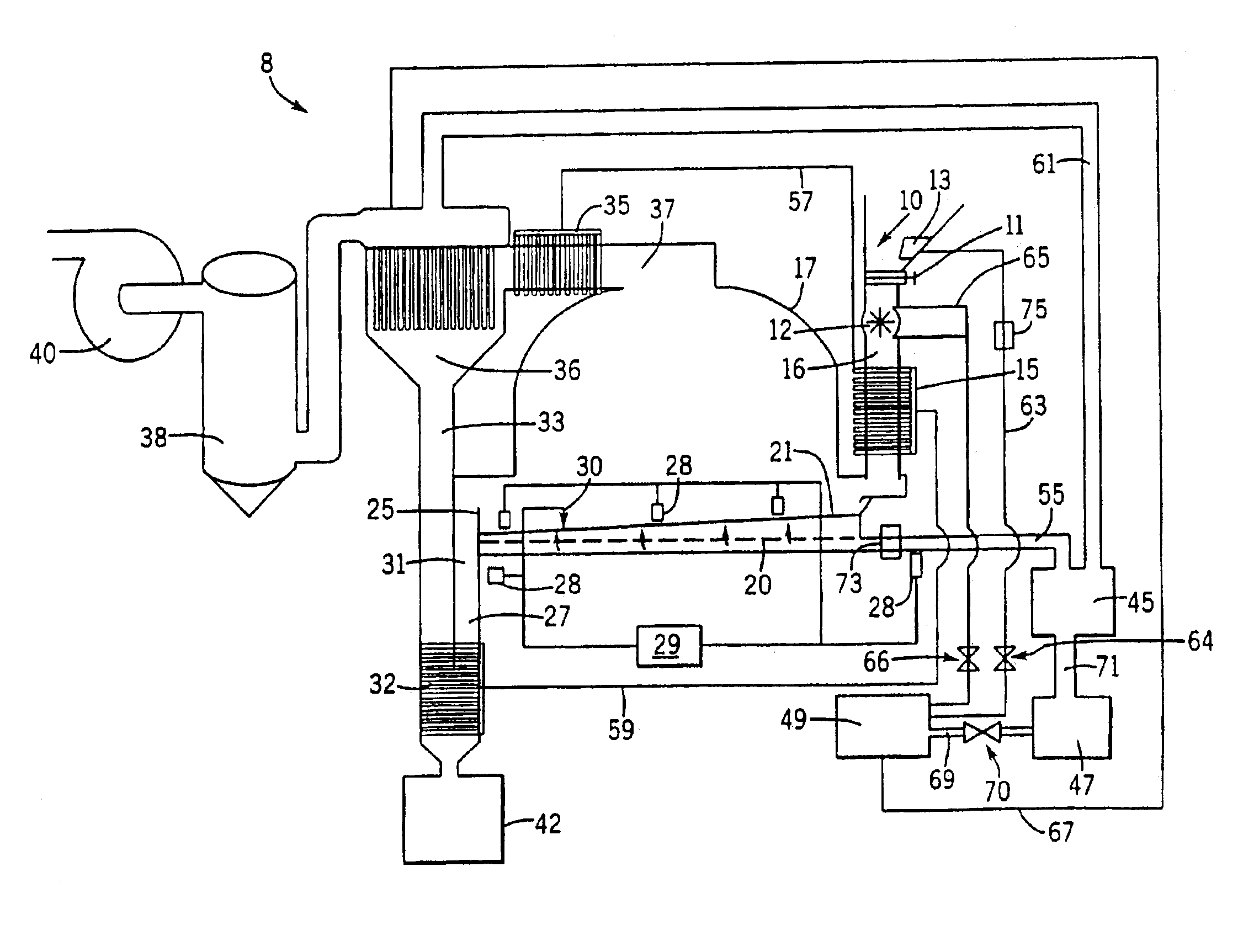
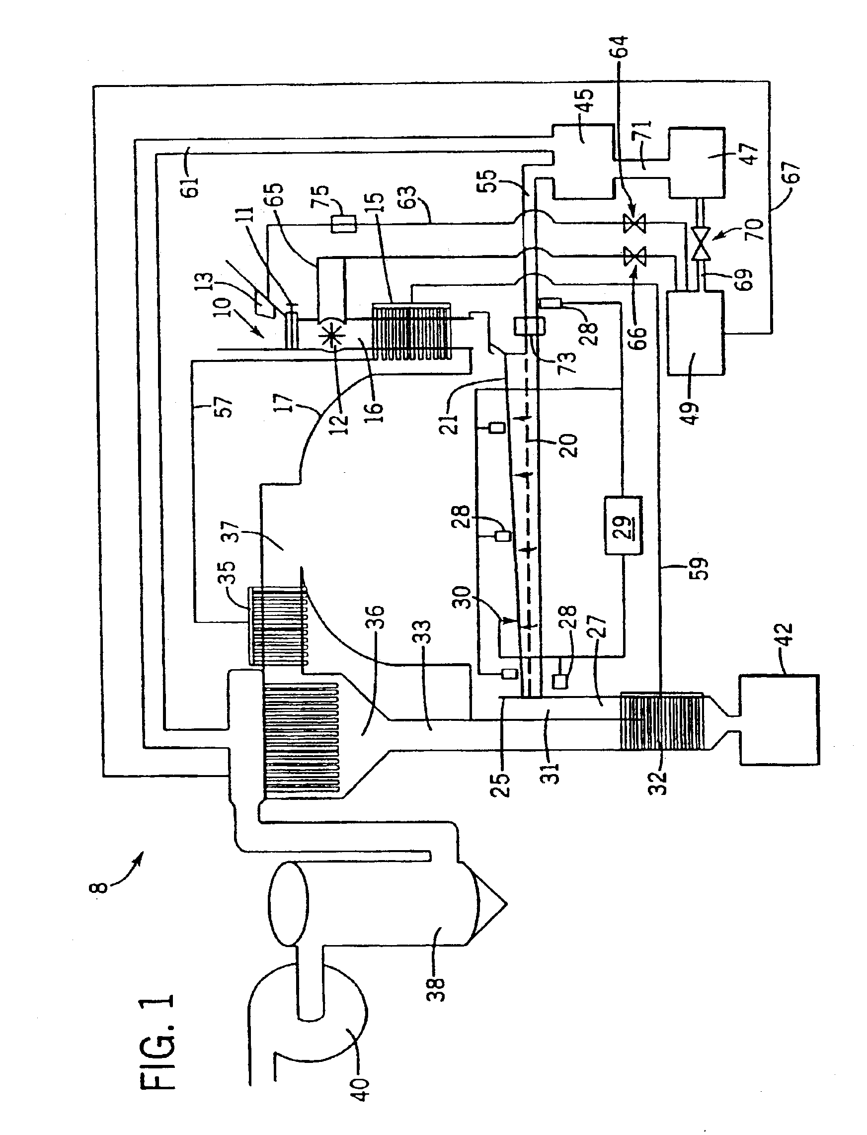
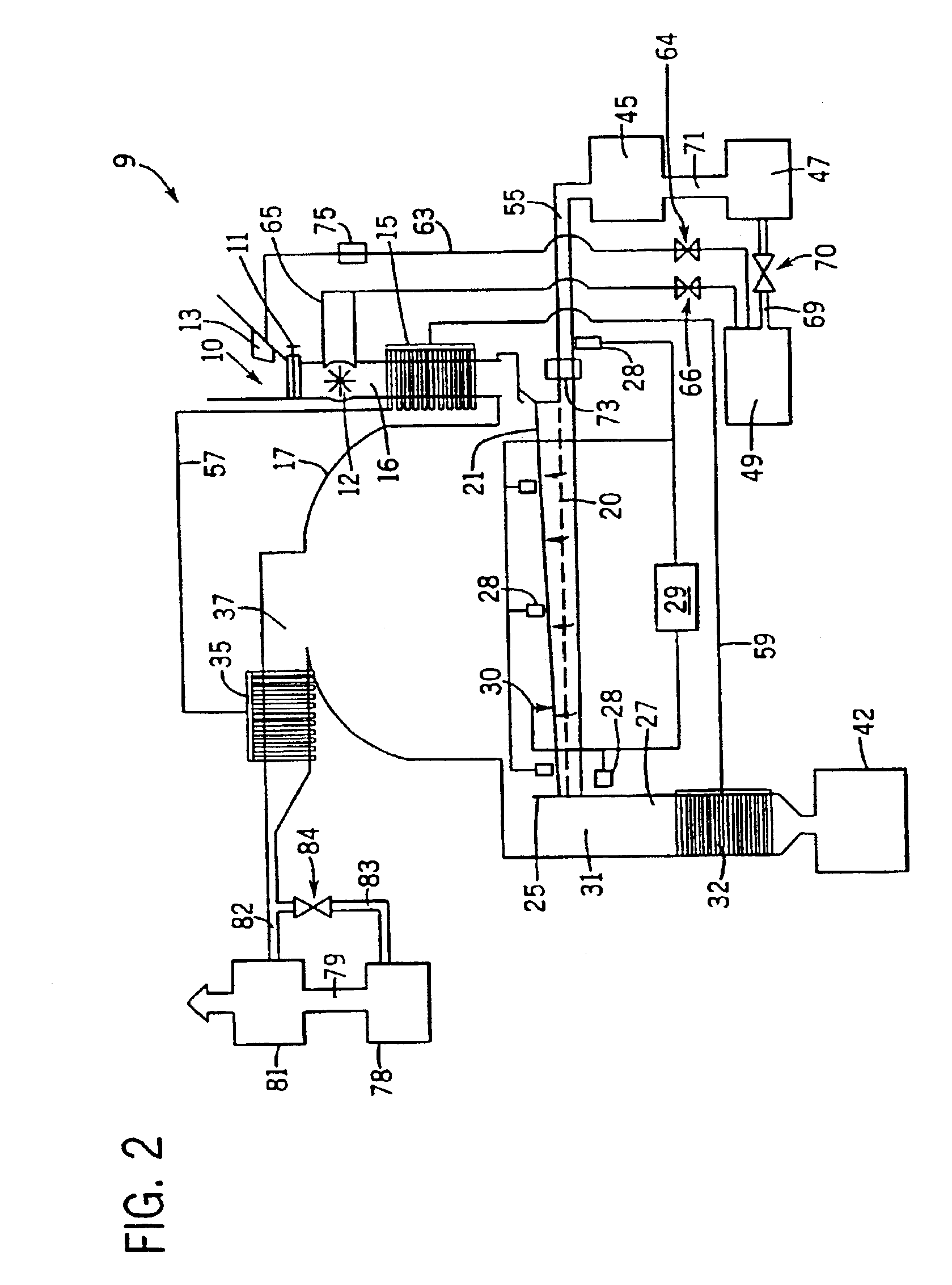
An apparatus for the application of heat to remove ammonia compounds from fly ash is disclosed. The apparatus includes a source of fly ash comprising particulates having ammonia compounds affixed to the fly ash particulates, a heating chamber including a treatment bed comprising a media having openings, a fly ash supply conduit for transferring fly ash from the source of fly ash to the treatment bed of the heating chamber, a source of heated air, an air supply conduit for providing a flow of heated air to the treatment bed of the heating chamber for contacting the fly ash on the treatment bed with the flow of heated air, a heated air conduit in communication with the heating chamber for transferring the flow of heated air from the heating chamber, and an ash removal conduit in communication with the heating chamber for transferring heated fly ash from the heating chamber.

Description

CROSS-REFERENCE TO RELATED APPLICATIONS[0001]This is a divisional application of application Ser. No. 09 / 807,643 filed Jul. 16, 2001, now U.S. Pat. No. 6,755,901, which is a 371 of PCT / US00 / 22398 filed Aug. 15, 2000 which claims priority from U.S. Provisional Patent Application No. 60 / 149,295 filed Aug. 17, 1999.BACKGROUND OF THE INVENTION[0002]This invention relates to the treatment of coal ash to remove ammonia compounds that contaminate the ash as part of post-combustion treatments of exhaust gases to remove nitrogen compounds.[0003]In 1990, the United States Environmental Protection Agency put into place the Clean Air Act Amendments which were designed to reduce the emissions of “greenhouse gases”. Among the emissions covered are the nitrogen compounds NO and NO2 referred to generically as NOx. NOx is generated through the combustion of coal and its generation is directly affected by combustion temperature, residency time and available oxygen. Several technologies have been deve...

Claims


Application Information

Patent Timeline
Patent Type & Authority Patents(United States)
IPC IPC(8): B01D53/56B09B3/00C22B7/02F23J1/00C04B18/08
CPCB01D53/56B09B3/00B09B3/0083C22B7/02Y02P10/20B09B3/40
Inventor RAMME, BRUCE W.FISHER, BRYAN C.
Owner WISCONSIN ELECTRIC POWER
Why Eureka
Try Eureka