Deterioration resistant chambers for inductively coupled plasma production

a technology of inductively coupled plasma and chambers, which is applied in the direction of diaphragms, metal-working apparatuses, metallic material coating processes, etc., can solve the problems of surface damage and degrade the performance of anodic coatings, and achieve the effect of improving the wall resistance to deterioration

Inactive Publication Date: 2005-09-20
ADVANCED ENERGY IND INC
View PDF3 Cites 35 Cited by
  • Summary
  • Abstract
  • Description
  • Claims
  • Application Information

AI Technical Summary

Benefits of technology

[0011]In one aspect of the invention is a plasma chamber with improved wall resistance to deterioration. The chamber includes a first housing portion, a seco

Problems solved by technology

In the course of plasma processing, surface damage occurs.
Furthermore, ion bombardment on the anodized metal housing results in pits that pierces the anodic l

Method used


Image

  • Deterioration resistant chambers for inductively coupled plasma production
  • Deterioration resistant chambers for inductively coupled plasma production
  • Deterioration resistant chambers for inductively coupled plasma production

Examples


Embodiment Construction

Overview

[0029]In one aspect of the invention is a method to construct plasma chambers with improved wall resistance to deterioration. In one embodiment of the invention, a chamber is made of an aluminum alloy having low concentrations of silicon, iron, manganese and chromium to address coating / substrate issues, comprises swaged-in cooling tubes to reduce thermal stress by improving thermal resistance, and comprises a plurality of dielectric gaps to decrease ion bombardment.

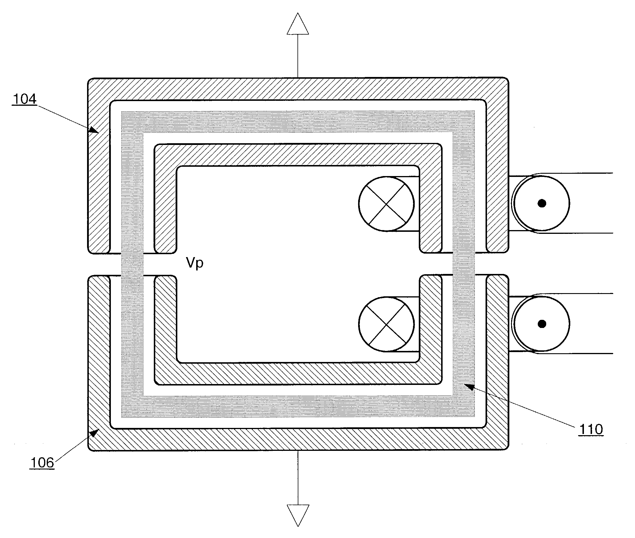
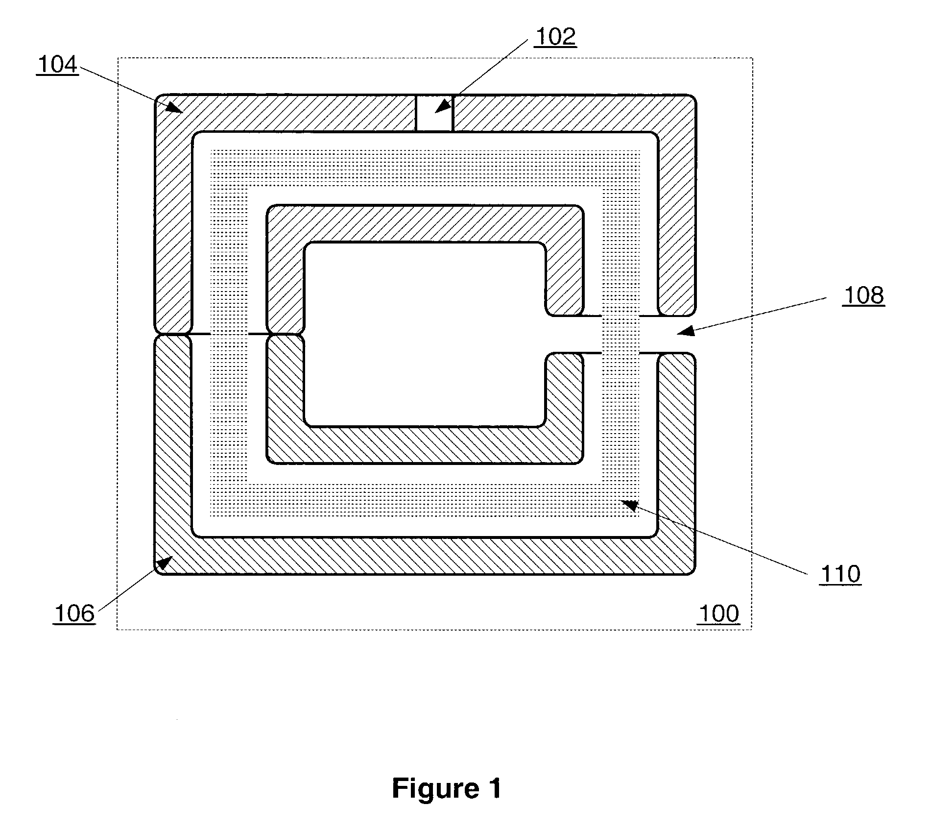
[0030]FIG. 1 illustrates a plasma chamber 100 in accordance with general embodiments of the invention. The plasma chamber 100 is formed from a first housing portion 104, and a second housing portion 106, and comprises at least one dielectric break 108 (only one shown) between the first and second housing portions 104, 106 to prevent induced current flow from forming in the plasma chamber 100. The housing portions 104, 106 are usually made of anodized aluminum.

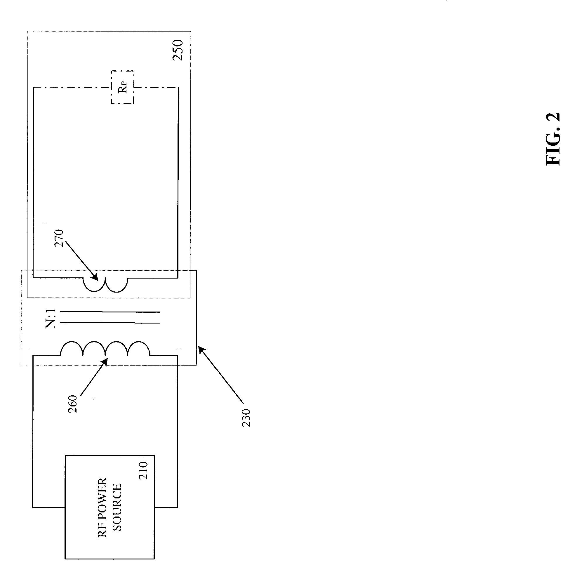
[0031]In steady state operation, the working gas is con...


PUM

PropertyMeasurementUnit
Concentrationaaaaaaaaaa
Electrical resistanceaaaaaaaaaa
Solubility (mass)aaaaaaaaaa

Abstract

In one aspect of the invention is a method to construct plasma chambers with improved wall resistance to deterioration. In one embodiment of the invention, a chamber is made of an aluminum alloy having low concentrations of elements that form non-soluble, intermetallic particles to address coating/substrate issues, has swaged-in cooling tubes to reduce thermal stress by improving thermal resistance, and has a plurality of dielectric gaps to decrease ion bombardment.

Description

[0001]This application is a continuation-in-part of application Ser. No. 10 / 284,821, filed on Oct. 31, 2002, now U.S. Pat. No. 6,802,366 entitled “Swage Method for Cooling Pipes”, and claims priority therefrom.BACKGROUND OF THE INVENTION[0002]1. Field[0003]Embodiments of this invention relate to the field of failure mechanisms found in chambers for inductively coupled plasma production, and more specifically, to a plasma chamber with an anodic coating with improved resistance to deterioration.[0004]2. Description of Related Art[0005]Inductively coupled plasmas (ICP) are routinely used in a number of different applications including production of activated gases, pollutant abatement and many others. In such devices, a coil is placed in close proximity to, around or within a vacuum chamber. When the coil is excited with radio frequency (RF), the electromagnetic fields induced around the coil sustain a gas plasma discharge within the vacuum apparatus. The plasma is coupled to the coil ...

Claims


Application Information

Patent Timeline
IPC IPC(8): B21C37/15B21D53/08B21D53/02B23P11/00B21J9/06B21J9/00F28F1/12F28F1/22
CPCB21C37/155B21D53/085B21J9/06B23P11/00F28F1/22B23P15/26Y10T29/4981F28F2275/025Y10T29/49375
Inventor GONZALEZ, JUAN JOSEDILLON, STEVESHABALIN, ANDREWMAUCK, JUSTINTOMASEL, FERNANDO GUSTAVO
Owner ADVANCED ENERGY IND INC
Why Eureka
Try Eureka