
Thermo-electrically cooled surface-enhanced raman spectroscopy sensor system to detect volatile organic compounds

a sensor system and raman spectroscopy technology, applied in the field oframan spectroscopy, can solve the problems of insufficient understanding of surface enhanced raman spectroscopy, inherently insensitive technique of raman spectroscopy, etc., and achieve the effect of increasing the volatility of analyte and minimizing the introduction of moisture and debris into the manifold

Inactive Publication Date: 2005-09-20
THE UNITED STATES OF AMERICA AS REPRESENTED BY THE SECRETARY OF THE NAVY
View PDF1 Cites 32 Cited by
  • Summary
  • Abstract
  • Description
  • Claims
  • Application Information

AI Technical Summary

Benefits of technology

[0008]In one embodiment, the thermoelectrically cooled surface-enhanced Raman spectrometer sensor system includes a gas source for providing an inert gas into a manifold having a semipermeable membrane, which minimizes the introduction of moisture and debris into the manifold. As inert gas flows through the manifold, negative pressure causes the analyte, which may be a gas or vapor, to be drawn into the manifold through the semipermeable membrane. The analyte and inert gas mix to create a gas mixture in the manifold. The semipermeable membrane may be heated to increase the volatility of the analyte, especially when the semipermeable membrane is in contact with liquid environments such as aqueous or saturated soil environments.

Problems solved by technology

Despite the advantages of Raman spectroscopy over other spectroscopic techniques and the technological advances in the area of Raman spectrometry, Raman spectroscopy is inherently an insensitive technique.
This phenomenon, called surface enhanced Raman spectroscopy (SERS), is still not understood despite intensive theoretical and experimental research.

Method used


Image

  • Thermo-electrically cooled surface-enhanced raman spectroscopy sensor system to detect volatile organic compounds
  • Thermo-electrically cooled surface-enhanced raman spectroscopy sensor system to detect volatile organic compounds
  • Thermo-electrically cooled surface-enhanced raman spectroscopy sensor system to detect volatile organic compounds

Examples


Embodiment Construction

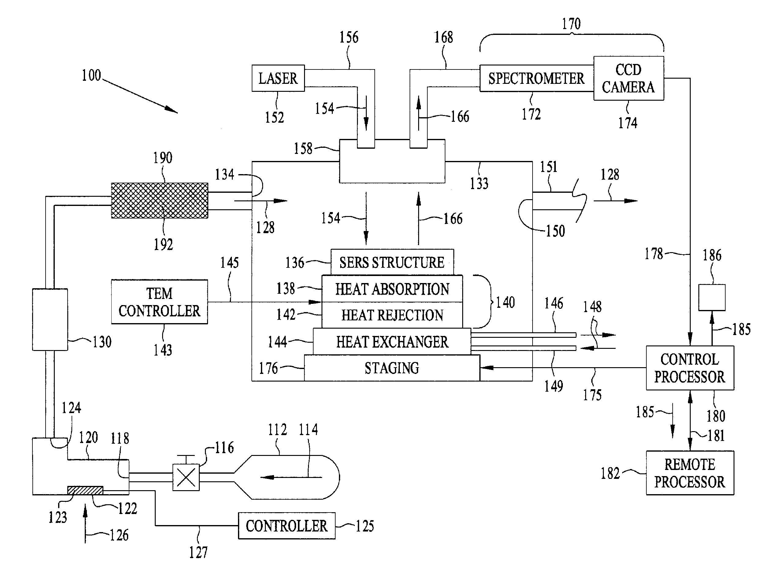
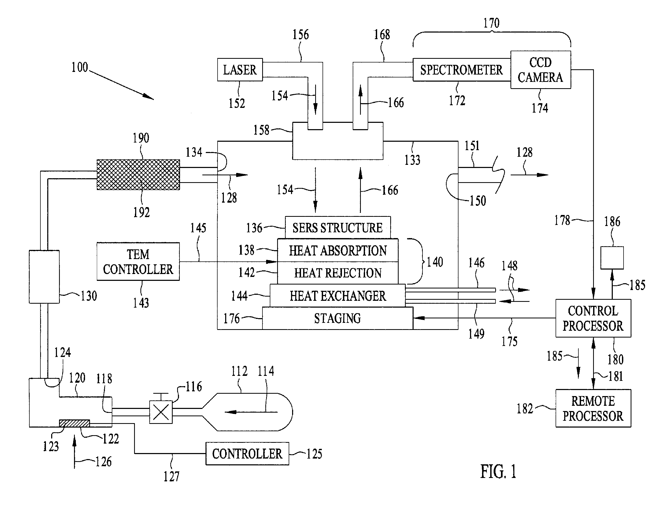
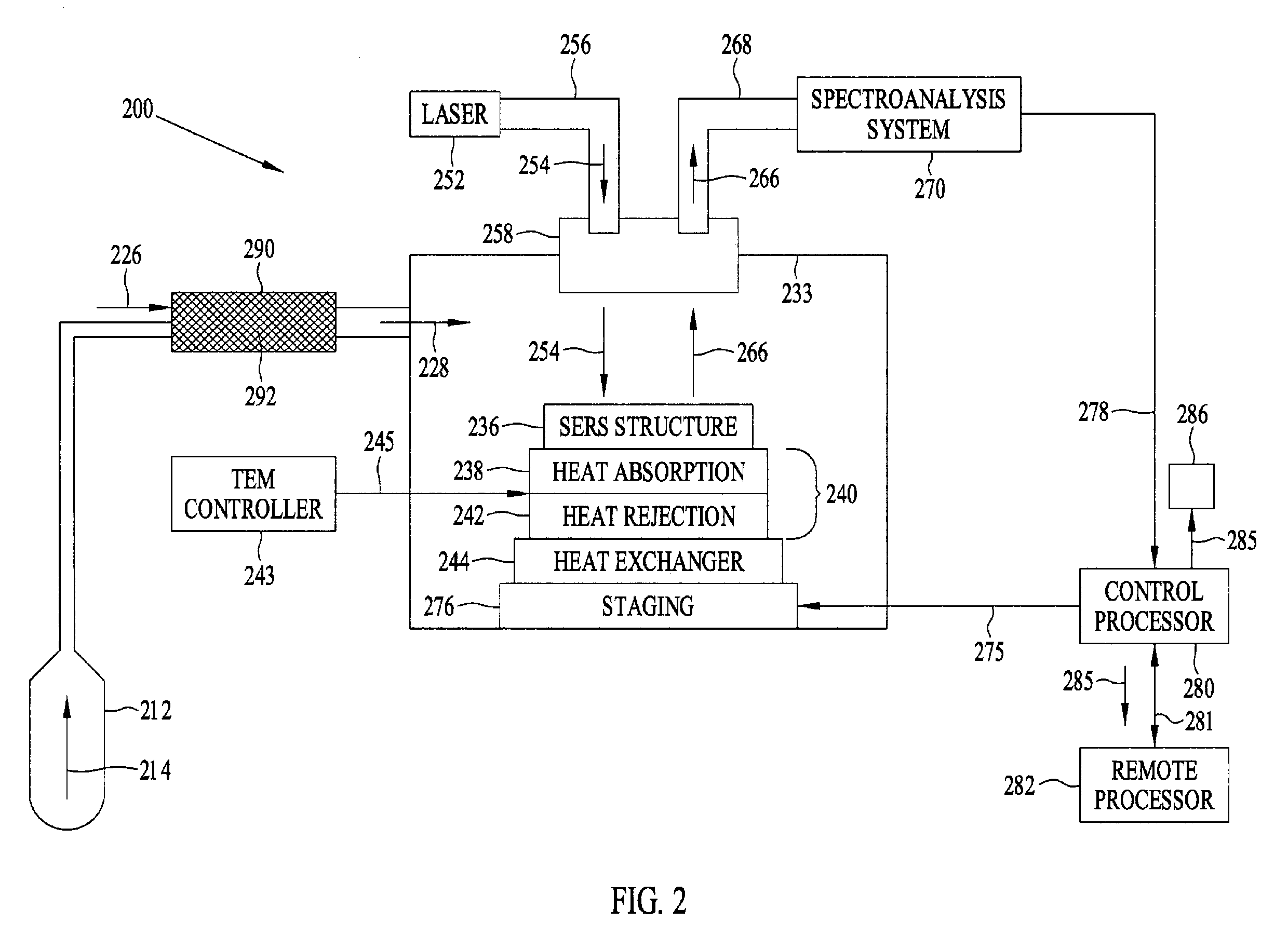
[0019]The thermoelectrically cooled surface-enhanced Raman spectrometer sensor system is described with reference to FIG. 1. Controlling the temperature of thermoelectric (TEM) cooler 140 facilitates condensation of selected analytes 126 that may be present in sample chamber 133, so that they may condense onto SERS structure 136, because different analytes condense at different temperatures. When in contact with each other, analyte 126 and SERS structure 136 may be stimulated by optical excitation signal 154 to produce optical emissions signal 166, which is unique to a particular analyte. Such optical emissions signal 166 may be detected by spectroanalysis system 170 and then correlated to the particular analyte 126 by control processor 180. Control processor 180 may transmit the SERS optical emissions signal 166 detected by spectroanalysis system 170 to remote processor 182 via signal line 181. When an analyte is in contact with the SERS structure 136, control processor 180 also ge...


PUM


Abstract

A thermoelectrically cooled surface-enhanced Raman spectrometer sensor system and method for monitoring of volatile organic compounds in gas, liquid, and soil environments. The sensor system comprises a means for providing an inert gas, a thermal desorption tube containing an adsorbate, and a sample chamber with a SERS structure. For liquid and soil environments, the sensor system also comprises a manifold having a semipermeable membrane for separating moisture from an analyte. An optical module mounted to the sample chamber directs an optical excitation signal for irradiating the SERS structure and receives a SERS optical emissions signal. Such optical emissions signal may be detected by a spectroanalysis system and correlated to a particular analyte by a control processor, which generates an alert signal containing a message that the presence of analyte has been detected. The control processor may also activate warning device, such as an audible siren or a visual alarm.

Description

CROSS REFERENCE TO RELATED APPLICATIONS[0001]This application is a continuation-in-part of commonly assigned U.S. patent application Ser. No. 10 / 133,705, entitled THERMO-ELECTRICALLY COOLED SURFACE ENHANCED RAMAN SPECTROSCOPY SENSOR SYSTEM, filed 26 Apr. 2002, a continuation-in-part of commonly assigned U.S. patent application Ser. No. 09 / 888,737, now U.S. Pat. No. 6,888,629 entitled SENSOR FOR PERFORMING SURFACE ENHANCED RAMAN SPECTROSCOPY AND METHOD FOR ACHIEVING SAME, filed 25 Jun. 2001, a continuation-in-part of commonly assigned U.S. patent application Ser. No. 09 / 805,665, now U.S. Pat. No. 6,614,523 entitled SENSOR FOR PERFORMING SURFACE ENHANCED RAMAN SPECTROSCOPY, filed 13 Mar. 2001, and a continuation-in-part of commonly assigned U.S. patent application Ser. No. 09 / 593,675, now U.S. Pat. No. 6,406,777 entitled A METAL AND GLASS STRUCTURE FOR USE IN SURFACE ENHANCED RAMAN SPECTROSCOPY AND METHOD FOR FABRICATING SAME, filed 14 Jun. 2000, and which are hereby incorporated by r...

Claims


Application Information

Patent Timeline
IPC IPC(8): G01J3/44G01N21/65
CPCG01J3/44G01N21/658G01J3/0286G01N2201/1211
Inventor BOSS, PAMELA A.LIEBERMAN, STEPHEN H.ANDREWS, JOHN M.ANDERSON, GREGORY WAYNE
Owner THE UNITED STATES OF AMERICA AS REPRESENTED BY THE SECRETARY OF THE NAVY
Learn More