Robust heterodyne interferometer optical gauge

a heterodyne interferometer and optical gauge technology, applied in the field of robust heterodyne interferometers, can solve the problems of heterodyne interferometer devices, measurement, and every optical pathlength, and achieve the effect of low thermal expansion coefficien

Inactive Publication Date: 2005-09-20
LOCKHEED MARTIN CORP
View PDF17 Cites 11 Cited by
  • Summary
  • Abstract
  • Description
  • Claims
  • Application Information

AI Technical Summary

Problems solved by technology

The major practical problem with high resolution interferometry is that every optical pathlength change in the system, including the ones that are not intended, are measured.
Typically, existing heterodyne interferometer devices are subject to thermal drift errors that limit their performance.
In addition, they consist of a precision assembly of critical components leading to high cost to manufacture.

Method used


Image

  • Robust heterodyne interferometer optical gauge
  • Robust heterodyne interferometer optical gauge
  • Robust heterodyne interferometer optical gauge

Examples


Embodiment Construction

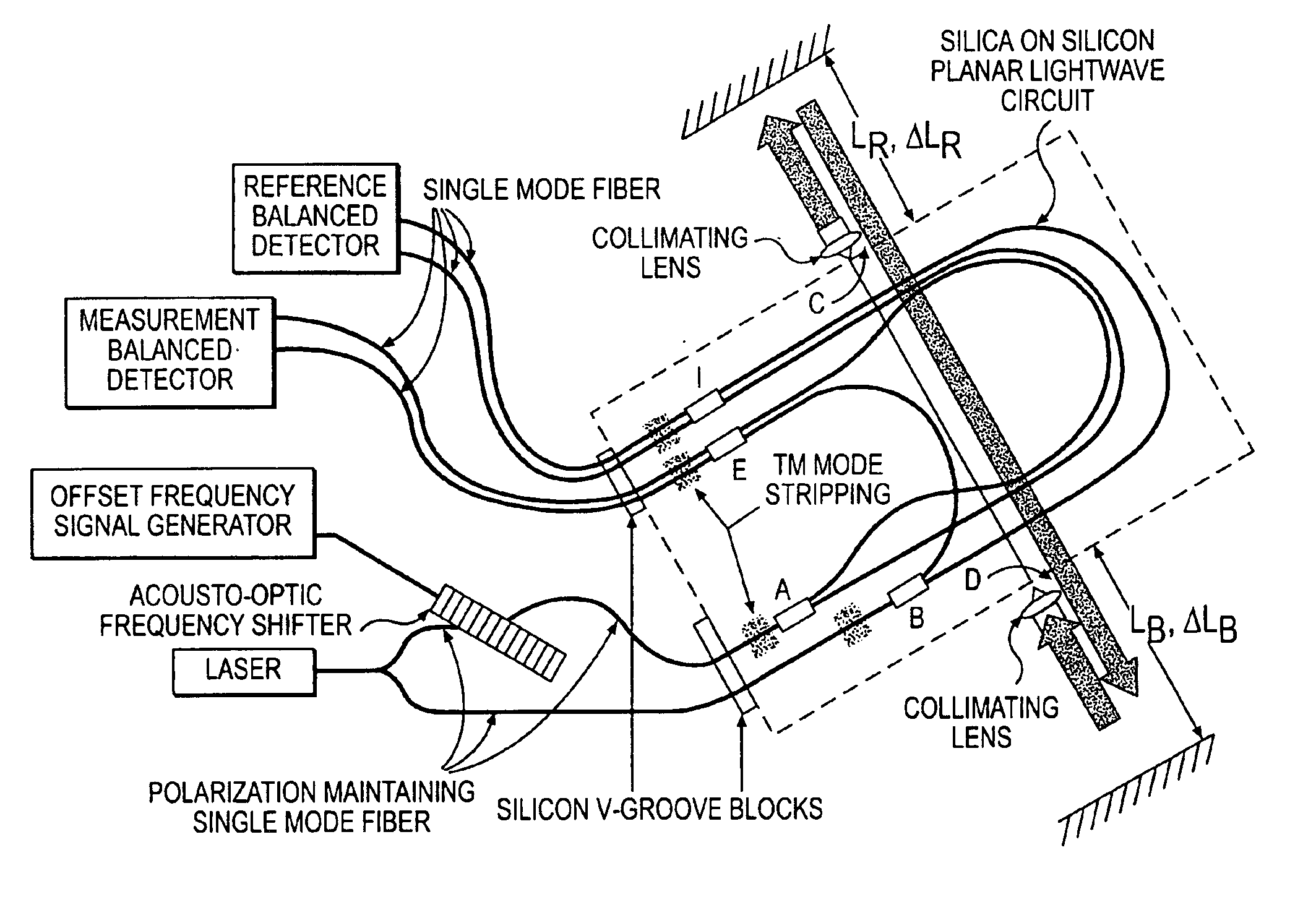
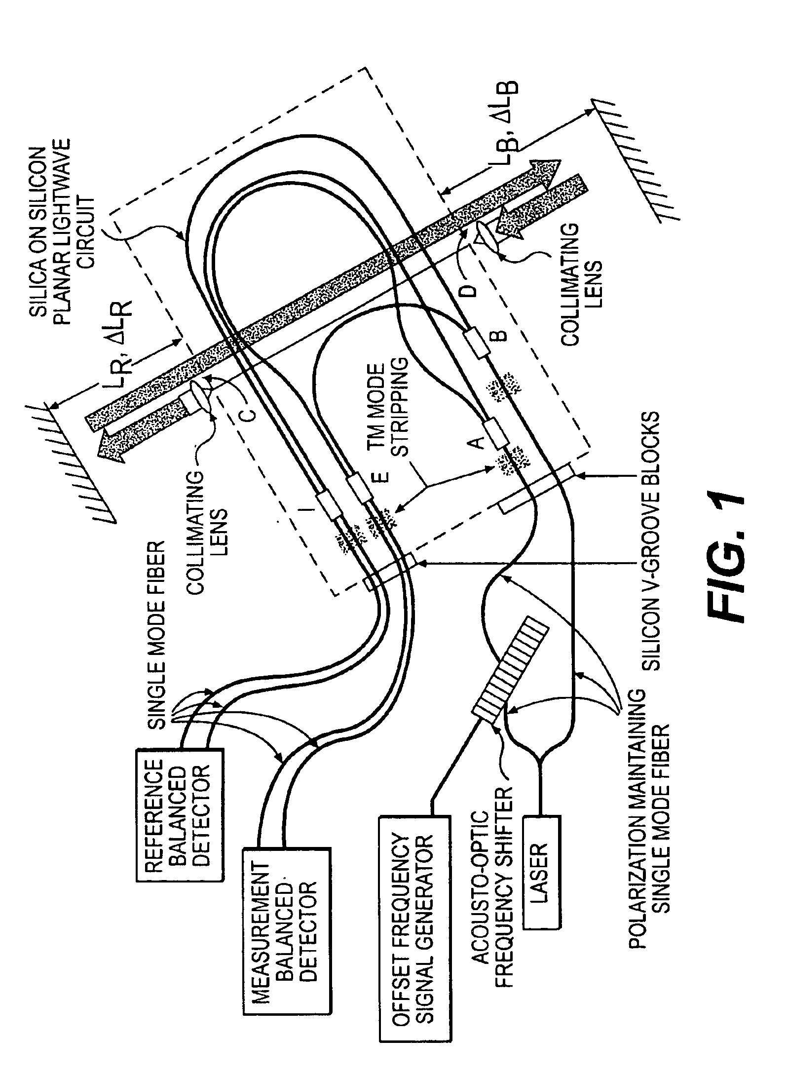
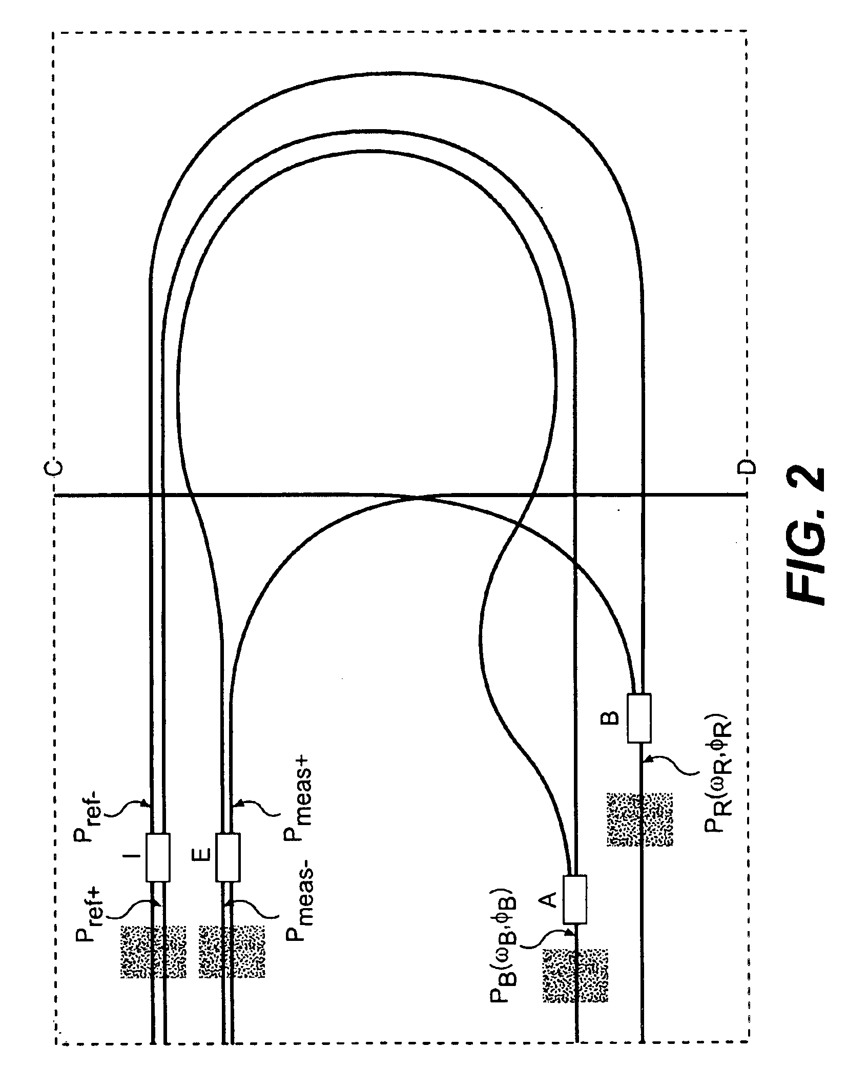
[0023]The present invention provides a solution to problems existing with known devices. Along these lines, the present invention can provide a small, lightweight and robust optical gauge. A planar lightwave circuit (PLC) according to the present invention replaces large bulk components typically utilized in known devices. Use of the PLC according to the present invention results in smaller devices that are less sensitive or insensitive to thermal changes. Additionally, a device according to the present invention can be fiber coupled to inputs and outputs, such as sensors and light sources, and contains few components. Features of the present invention can permit devices according to the present invention to measure distance changes, for example, that are on the order of about one-millionth of the wavelength of light utilized in an application of the device.

[0024]The present invention can provide a device that can be utilized in the control of large structures by providing position,...


PUM


Abstract

A method for performing optical signal and beam distribution in a heterodyne interferometer. A planar lightwave circuit is provided including a plurality of waveguide optical transmission elements and an input coupler and an output coupler arranged along the optical transmission elements. Optical pathlengths of the transmission elements are matched between the input coupler and the output coupler to compensate for thermal effects. Reference and measurement optical phases are determined employing the input coupler and the output coupler.

Description

FIELD OF THE INVENTION[0001]The present invention relates to a robust heterodyne interferometer for very high resolution non-contact measurement of distances.BACKGROUND OF THE INVENTION[0002]Heterodyne Interferometry measures the phase of a continuous signal for as long as the signal remains stable over all portions of a reference path and a measurement path. The major practical problem with high resolution interferometry is that every optical pathlength change in the system, including the ones that are not intended, are measured. After the beams are split in the interferometer, movement of optical components, especially mirrors, add or subtract optical path length from one of the two beams separately, resulting in a signal that is unrelated to the measurement. Therefore, stability of optical components in the separate legs of the interferometer is critical, as described in J. D. Trolinger, Ultra High Resolution Interferometry, Proc. SPIE Vol. 2816, pp114-123 (1996).[0003]Typically,...

Claims


Application Information

Patent Timeline
Patent Type & Authority Patents(United States)
IPC IPC(8): G01D5/353G01B9/02G01D5/26G02B6/125G02B6/14
CPCG01D5/35303G02B6/125G02B6/14G01B9/02051G01B9/02003G01B9/0207G01B2290/60
Inventor BELL, JR., RAYMOND MARKPERKINS, PATRICK ELLIOTTAMES, LAWRENCE LOWELLANDERSON, WILLIAM WALTER
Owner LOCKHEED MARTIN CORP
Why Eureka
Try Eureka